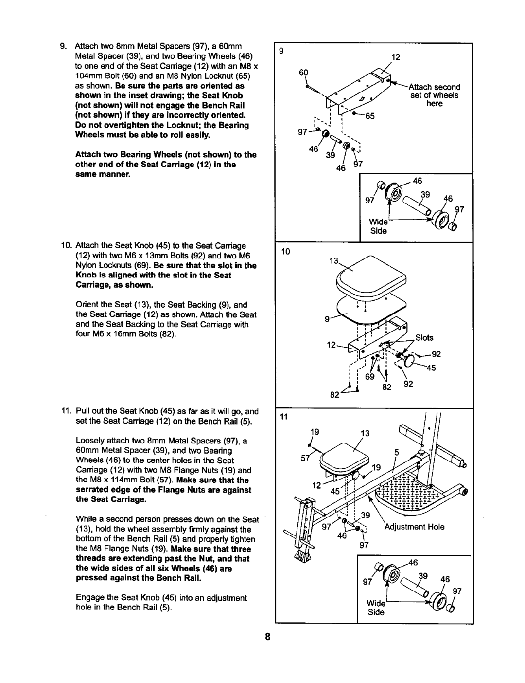
g. Attach two 8mm Metal Spacers (97), a 60mm | 9 | |
Metal Spacer (39), and two Bearing Wheels (46) | ||
| ||
to one end of the Seat Carriage (12) with an M8 x |
| |
104mm Bolt (60) and an M8 Nylon Locknut (65) |
| |
as shown. Be sure the parts are oriented as |
| |
shown in the inset drawing; the Seat Knob |
| |
(not shown) will not engage the Bench Rail |
| |
(not shown) if they are incorrectly oriented. |
| |
Do not overtighten the Locknut; the Bearing |
| |
Wheels must be able to roll easily. |
| |
Attach two Bearing Wheels (not shown) to the |
| |
other end of the Seat Carriage (12) in the |
| |
same manner. |
|
|
|
| 12 |
6 L | _Attach |
| second |
./_. | ,// | set of wheels | |
| _ |
| here |
•
97
/_1 46
10.Attach the Seat Knob (45) to the Seat Carriage (12) with two M6 x 13mm Bolts (92) and two M6
Nylon Locknuts (69). Be sure that the slot in the Knob is aligned with the slot in the Seat Carriage, as shown.
Orient the Seat (13), the Seat Backing (9), and the Seat Carriage (12) as shown. Attach the Seat and the Seat Backing to the Seat Carriage with four M6 x 16mm Bolts (82).
11.Pull out the Seat Knob (45) as far as itwill go, and set the Seat Carriage (12) on the Bench Rail (5).
Loosely attach two 8mm Metal Spacers (97), a 60mm Metal Spacer (39), and two Bearing Wheels (46) to the center holes in the Seat Carriage (12) with two M8 Flange Nuts (19) and the M8 x 114mm Bolt (57). Make sure that the serrated edge of the Flange Nuts are against the Seat Carriage.
While a second person presses down on the Seat (13), hold the wheel assembly firmly against the bottomof the Bench Rail (5) and propedy tighten the M8 Flange Nuts (19). Make sure that three threads are extending past the Nut, and that
the wide sides of all six Wheels (46) are pressed against the Bench Rail.
Engage the Seat Knob (45) into an adjustment hole in the Bench Rail (5).
10
Slots
11 19 | 13 | /// |
ustmentHole
97
_/(_ | ._6 97 |
8