Section
2 Assembly
WARNING
To prevent personal injury or property damage, do not attempt to start the engine until all assembly steps are complete and you have read and understand the safety, controls and operating instructions in this manual.
INTRODUCTION
Please carefully follow these assembly steps to properly prepare your machine for use. We recommend that you read this Section in its entirety before begin- ning assembly.
NOTE: All references to left, right, front and rear of the machine are determined by standing behind the handlebars and facing the direction of forward travel.
INSPECTION AFTER DELIVERY
When unpacking the machine, inspect for shipping damage or missing parts. If you find any damage, or if parts are missing, notify the White Outdoor Dealer who sold you the machine.
TOOLS/MATERIALS NEEDED:
•Wire Cutter
•7/16” Wrench
•3/8” Wrench
•Two 1/2” Wrenches
•Scissors or Pen Knife
•
•Motor Oil (see Step 5)
•Tire Gauge
ASSEMBLY STEPS
IMPORTANT: MOTOR OIL MUST BE ADDED TO THE ENGINE BEFORE IT IS STARTED. FOLLOW INSTRUCTIONS IN THIS “ASSEMBLY” SECTION.
STEP 1: Unpacking Mower
NOTE: LEFT and RIGHT sides of the unit are as viewed from the operator’s posi- tion behind the handlebars.
1.Cut plastic banding, open box flaps and remove cardboard liners. Remove any staples securing carton to wood pal- let and lift off carton. Cut metal straps securing unit to pallet. Leave unit on pal- let during assembly (to safely remove unit from pallet, wait until you have com- pleted assembly steps
2.Remove hardware bag and check contents against illustrated parts list on next page.
3.Remove any protective packaging from around the handlebars. Cut the plastic tie straps holding the four long control rods to the handlebars. Do not remove the two long handlebar struts that are attached to the top of the handlebars.
4.Check for any small parts before dis- carding the carton or cardboard liners.
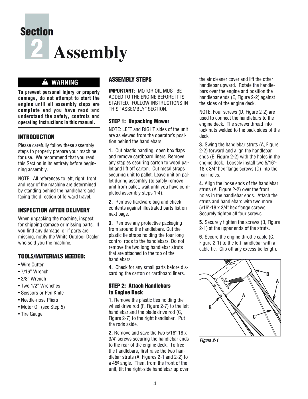
STEP 2: Attach Handlebars to Engine Deck
1.Remove the plastic ties holding the wheel drive rod (F, Figure
2.Remove and save the two
the air cleaner cover and lift the other handlebar upward. Rotate the handle- bars over the engine and position the handlebar ends (E, Figure
NOTE: Four screws (D, Figure
3.Swing the handlebar struts (A, Figure
18x 3/4" hex flange screws (D) into the rear holes.
4.Align the loose ends of the handlebar struts (A, Figure
5.Securely tighten the screws (B, Figure
6.Secure the engine throttle cable (C, Figure
B |
A |
A |
B |
C |
Figure |
4