Replacing the drive wheel
1.Complete steps 1 through 6 in Replacing blades.
2.Remove the snap ring which secures the lower wheel to the gearbox output shaft.
3.Pull the wheel off of the gearbox output shaft using a suitable puller.
4.Inspection: Examine the wheel for damage on its drive edge, shoulder, or the shaft boss. Replace if any faults are found.
5.Reinstall the wheel by pressing and/or tapping it back onto the shaft using a
6.Reinstall the snap ring which retains the wheel on the shaft.
7.Complete steps 7 through 14 of Replacing blades and any steps in Adjusting blade tracking, as needed to complete the installation.
Installing the vertical sawing table
1.Disconnect the saw from its electrical power source to prevent accidental motor
2.Raise the saw to full vertical position and lock in position using the quick lock valve.
3.Remove the two flat head cap screws which hold the small cutting plate to the bearing seat.
4.Place the large vertical cutting plate in position and use the two flat head cap screws to attach it firmly to the bearing seat.
5.Reconnect the saw to electrical power and it is ready to use as a vertical band saw.
Replacing idler wheel or bearings
1.Complete steps 1 through 6 in Replacing blades.
2.Remove center bolt and washer from the idler wheel.
3.Remove the two bolts which hold the sliding plate draw block in the sliding plate and remove the wheel and draw block from the saw as an assembly.
4.Using a suitable puller or press, pull or press the wheel, complete with bearings, off of the draw block.
5.Using a suitable puller, remove the two bearings from inside the wheel hub.
6.Inspections: Inspect the bearings for evidence of leakage and turn them to feel for roughness or other internal flaws. Replace if leaking or roughness is felt.
Examine the wheel for damage on its drive edge, shoul- der, or the bearing mounting boss. Replace if any faults are found.
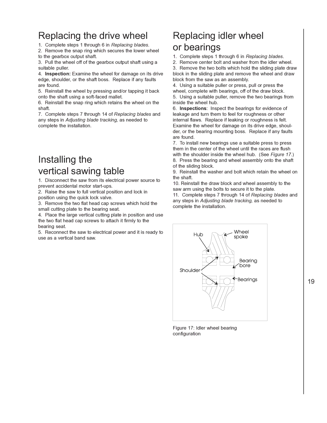
7.To install new bearings use a suitable press to press them in the center of the wheel until the races are flush with the shoulder inside the wheel hub. (See Figure 17.)
8.Press the bearing and wheel assembly onto the shaft of the sliding block.
9.Reinstall the washer and bolt which retain the wheel on the shaft.
10.Reinstall the draw block and wheel assembly to the saw arm using the bolts to secure it to the plate.
11.Complete steps 7 through 14 of Replacing blades and any steps in Adjusting blade tracking, as needed to complete the installation.
Figure 17: Idler wheel bearing configuration
19