eventually catch the thrust shaft and allow you to open or close the locking jaw at its new lead screw position.
When you slide the jaw to a new position, you can see where the nearest lead screw groove is by looking through the slot above the lead screw. (See Figure 1.)
Changing the locking jaw location:
1.Lift the quick release handle.
2.Slide the jaw until it contacts the workpiece.
3.Turn the lead screw handle until the thrust shaft drops into a groove.
4.Further turning of the lead screw handle will either clamp or release the workpiece in the vise. Turn clockwise to increase clamping pressure. Turn counterclockwise to release clamping pressure.
Adjusting stationary jaw: straight cuts
For accurate right angle or "straight" cutting, adjust the vise as follows:
1.Disconnect the saw from its electrical power source to prevent accidental
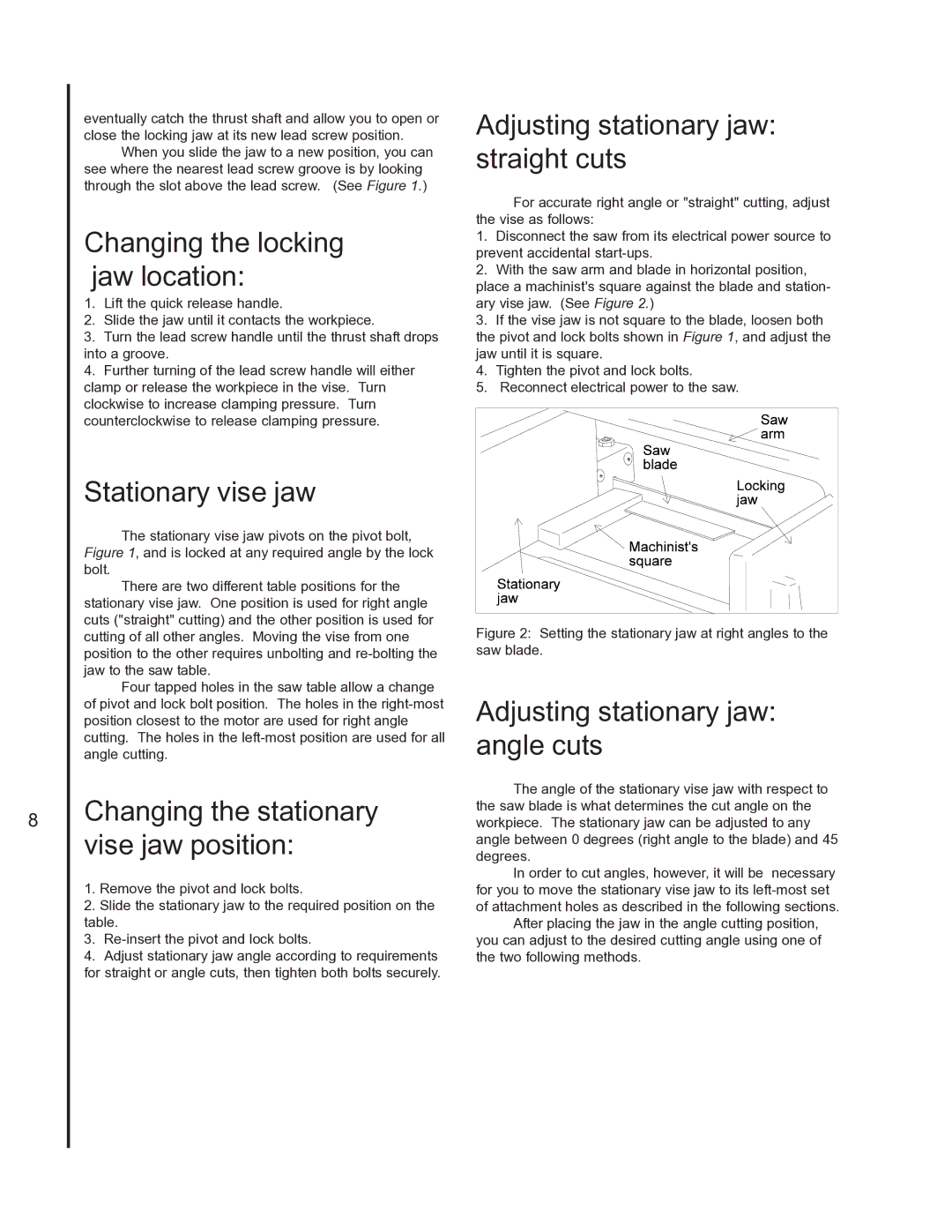
2.With the saw arm and blade in horizontal position, place a machinist's square against the blade and station- ary vise jaw. (See Figure 2.)
3.If the vise jaw is not square to the blade, loosen both the pivot and lock bolts shown in Figure 1, and adjust the jaw until it is square.
4.Tighten the pivot and lock bolts.
5.Reconnect electrical power to the saw.
8
Stationary vise jaw
The stationary vise jaw pivots on the pivot bolt, Figure 1, and is locked at any required angle by the lock bolt.
There are two different table positions for the stationary vise jaw. One position is used for right angle cuts ("straight" cutting) and the other position is used for cutting of all other angles. Moving the vise from one position to the other requires unbolting and
Four tapped holes in the saw table allow a change of pivot and lock bolt position. The holes in the
Changing the stationary vise jaw position:
1.Remove the pivot and lock bolts.
2.Slide the stationary jaw to the required position on the table.
3.
4.Adjust stationary jaw angle according to requirements for straight or angle cuts, then tighten both bolts securely.
Figure 2: Setting the stationary jaw at right angles to the saw blade.
Adjusting stationary jaw: angle cuts
The angle of the stationary vise jaw with respect to the saw blade is what determines the cut angle on the workpiece. The stationary jaw can be adjusted to any angle between 0 degrees (right angle to the blade) and 45 degrees.
In order to cut angles, however, it will be necessary for you to move the stationary vise jaw to its
After placing the jaw in the angle cutting position, you can adjust to the desired cutting angle using one of the two following methods.
