CASTER WHEEL MAINTENANCE
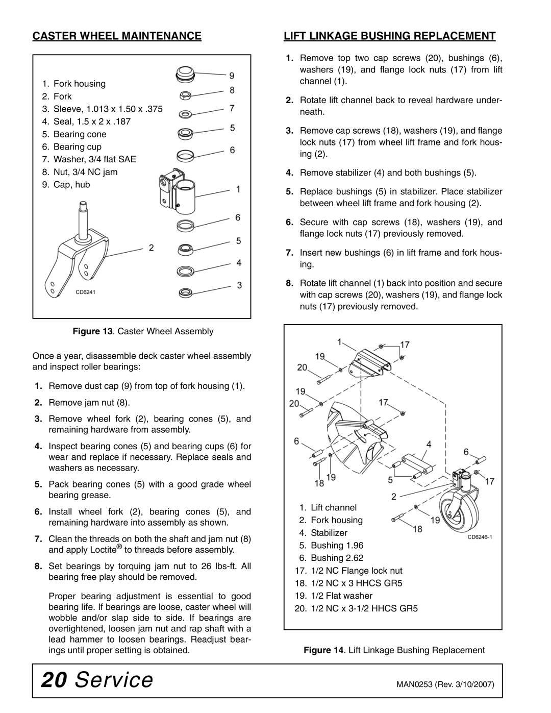
1.Fork housing
2.Fork
3.Sleeve, 1.013 x 1.50 x .375
4.Seal, 1.5 x 2 x .187
5.Bearing cone
6.Bearing cup
7.Washer, 3/4 flat SAE
8.Nut, 3/4 NC jam
9.Cap, hub
Figure 13. Caster Wheel Assembly
Once a year, disassemble deck caster wheel assembly and inspect roller bearings:
1.Remove dust cap (9) from top of fork housing (1).
2.Remove jam nut (8).
3.Remove wheel fork (2), bearing cones (5), and remaining hardware from assembly.
4.Inspect bearing cones (5) and bearing cups (6) for wear and replace if necessary. Replace seals and washers as necessary.
5.Pack bearing cones (5) with a good grade wheel bearing grease.
6.Install wheel fork (2), bearing cones (5), and remaining hardware into assembly as shown.
7.Clean the threads on both the shaft and jam nut (8) and apply Loctite® to threads before assembly.
8.Set bearings by torquing jam nut to 26 lbs-ft. All bearing free play should be removed.
Proper bearing adjustment is essential to good bearing life. If bearings are loose, caster wheel will wobble and/or slap side to side. If bearings are overtightened, loosen jam nut and rap shaft with a lead hammer to loosen bearings. Readjust bear- ings until proper setting is obtained.
LIFT LINKAGE BUSHING REPLACEMENT
1.Remove top two cap screws (20), bushings (6), washers (19), and flange lock nuts (17) from lift channel (1).
2.Rotate lift channel back to reveal hardware under- neath.
3.Remove cap screws (18), washers (19), and flange lock nuts (17) from wheel lift frame and fork hous- ing (2).
4.Remove stabilizer (4) and both bushings (5).
5.Replace bushings (5) in stabilizer. Place stabilizer between wheel lift frame and fork housing (2).
6.Secure with cap screws (18), washers (19), and flange lock nuts (17) previously removed.
7.Insert new bushings (6) in lift frame and fork hous- ing.
8.Rotate lift channel (1) back into position and secure with cap screws (20), washers (19), and flange lock nuts (17) previously removed.
1.Lift channel
2.Fork housing
4.Stabilizer
5.Bushing 1.96
6.Bushing 2.62
17.1/2 NC Flange lock nut
18.1/2 NC x 3 HHCS GR5
19.1/2 Flat washer
20.1/2 NC x
Figure 14. Lift Linkage Bushing Replacement
20 Service | MAN0253 (Rev. 3/10/2007) |
|
|