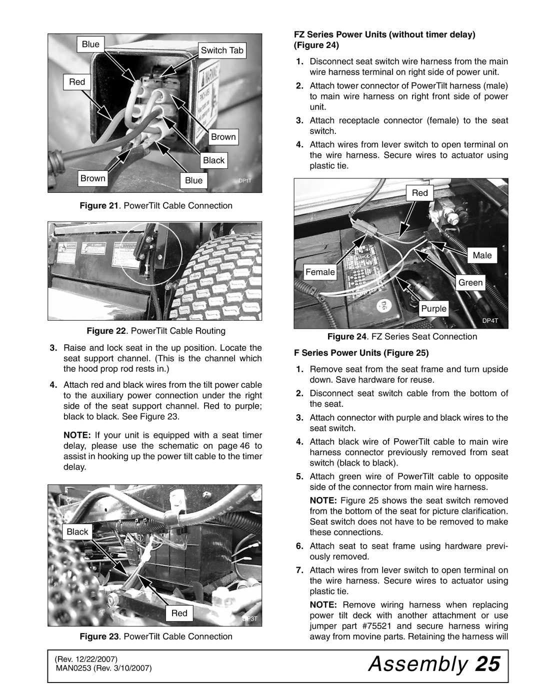
Blue | Switch Tab | |
| ||
Red |
|
|
|
| Brown |
|
| Black |
Brown | Blue | DP1T |
Figure 21. PowerTilt Cable Connection
Figure 22. PowerTilt Cable Routing
3.Raise and lock seat in the up position. Locate the seat support channel. (This is the channel which the hood prop rod rests in.)
4.Attach red and black wires from the tilt power cable to the auxiliary power connection under the right side of the seat support channel. Red to purple; black to black. See Figure 23.
NOTE: If your unit is equipped with a seat timer delay, please use the schematic on page 46 to assist in hooking up the power tilt cable to the timer delay.
Black
Red
DP3T
Figure 23. PowerTilt Cable Connection
FZ Series Power Units (without timer delay) (Figure 24)
1.Disconnect seat switch wire harness from the main wire harness terminal on right side of power unit.
2.Attach tower connector of PowerTilt harness (male) to main wire harness on right front side of power unit.
3.Attach receptacle connector (female) to the seat switch.
4.Attach wires from lever switch to open terminal on the wire harness. Secure wires to actuator using plastic tie.
Red |
Male |
Female |
Green |
Purple |
DP4T |
Figure 24. FZ Series Seat Connection
F Series Power Units (Figure 25)
1.Remove seat from the seat frame and turn upside down. Save hardware for reuse.
2.Disconnect seat switch cable from the bottom of the seat.
3.Attach connector with purple and black wires to the seat switch.
4.Attach black wire of PowerTilt cable to main wire harness connector previously removed from seat switch (black to black).
5.Attach green wire of PowerTilt cable to opposite side of the connector from main wire harness.
NOTE: Figure 25 shows the seat switch removed from the bottom of the seat for picture clarification. Seat switch does not have to be removed to make these connections.
6.Attach seat to seat frame using hardware previ- ously removed.
7.Attach wires from lever switch to open terminal on the wire harness. Secure wires to actuator using plastic tie.
NOTE: Remove wiring harness when replacing power tilt deck with another attachment or use jumper part #75521 and secure harness wiring away from movine parts. Retaining the harness will
(Rev. 12/22/2007) MAN0253 (Rev. 3/10/2007)