E. Electrical Switch (optional)
Although the power switch on your router can be turned on and off each time you use The Rebel®, the optional switch (Item Number W2001) offers greater convenience and safety. The optional switch is avail- able through your retailer.
The switch assembly consists of a guarded rocker type switch with removable key, three prong 110 volt female cord and three prong 110 volt male power cord.
Step 1 - Mount the electrical switch in the right front leg opening. To mount the switch, feed the male and female cords through the leg open- ing and snap the switch plate into place.
Figure 9.
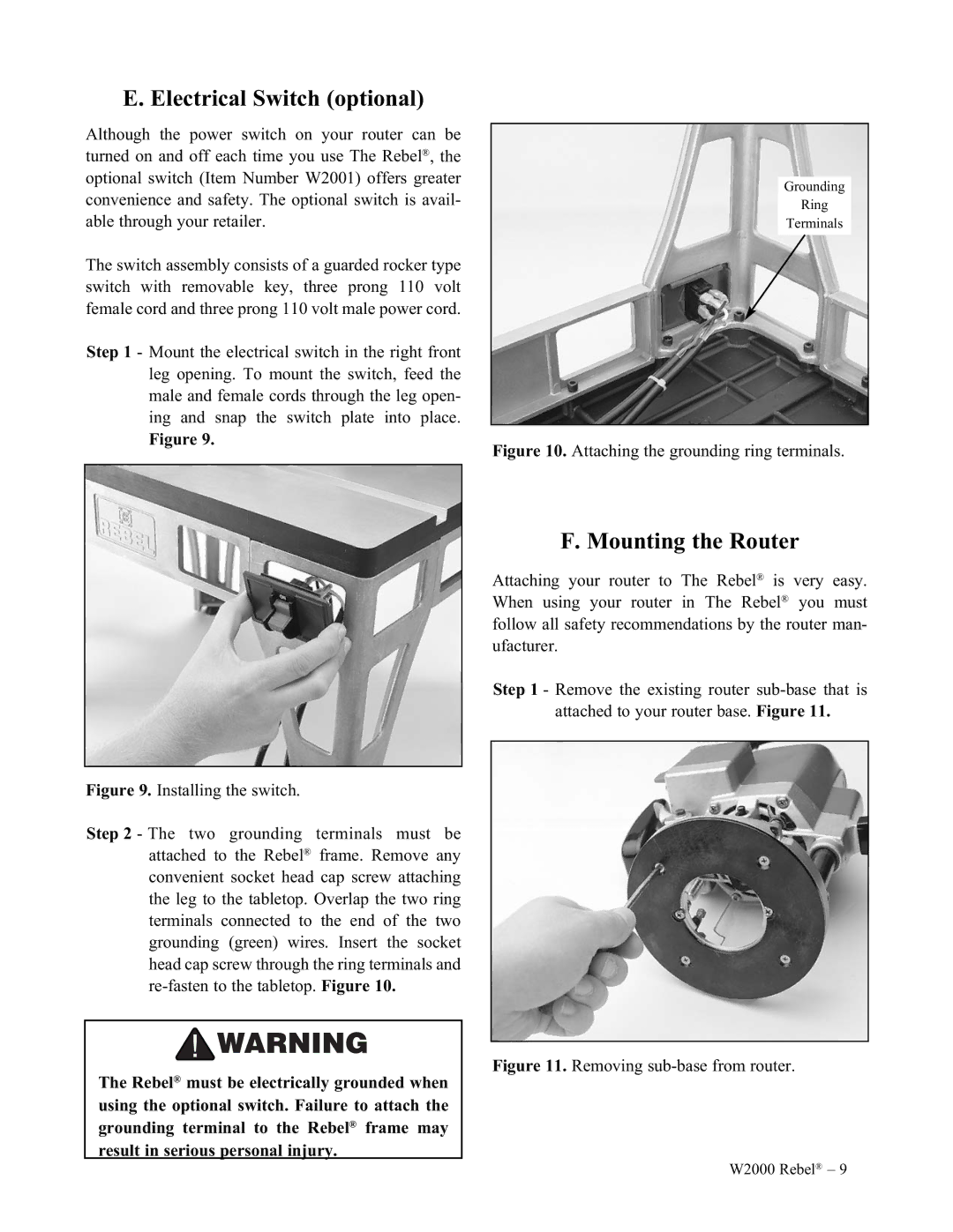
Grounding
Ring
Terminals
Figure 10. Attaching the grounding ring terminals.
Figure 9. Installing the switch.
Step 2 - The two grounding terminals must be attached to the Rebel® frame. Remove any convenient socket head cap screw attaching the leg to the tabletop. Overlap the two ring terminals connected to the end of the two grounding (green) wires. Insert the socket head cap screw through the ring terminals and re-fasten to the tabletop. Figure 10.
The Rebel® must be electrically grounded when using the optional switch. Failure to attach the grounding terminal to the Rebel® frame may result in serious personal injury.
F. Mounting the Router
Attaching your router to The Rebel® is very easy. When using your router in The Rebel® you must follow all safety recommendations by the router man- ufacturer.
Step 1 - Remove the existing router
Figure 11. Removing sub-base from router.
W2000 Rebel® – 9