Step 2 - Center the
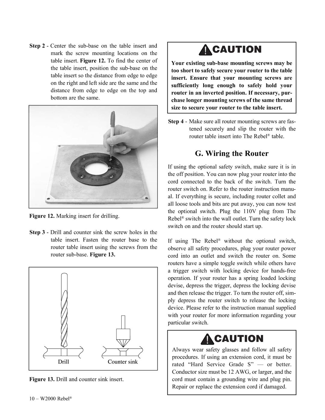
Figure 12. Marking insert for drilling.
Step 3 - Drill and counter sink the screw holes in the table insert. Fasten the router base to the router table insert using the screws from the router sub-base. Figure 13.
Figure 13. Drill and counter sink insert.
Your existing
Step 4 - Make sure all router mounting screws are fas- tened securely and slip the router with the router table insert into The Rebel® table.
G. Wiring the Router
If using the optional safety switch, make sure it is in the off position. You can now plug your router into the cord connected to the back of the switch. Turn the router switch on. Refer to the router instruction manu- al. If everything is secure, including router collet and all loose tools and bits are put away, you can now test the optional switch. Plug the 110V plug from The Rebel® switch into the wall outlet. Turn the safety lock switch on and the router should start up.
If using The Rebel® without the optional switch, observe all safety procedures, plug your router power cord into an outlet and switch the router on. Some routers have a simple toggle switch while others have a trigger switch with locking device for
Always wear safety glasses and follow all safety procedures. If using an extension cord, it must be rated “Hard Service Grade S” — or better. Conductor size must be 12 AWG, or larger, and the cord must contain a grounding wire and plug pin. Repair or replace the extension cord if damaged.
10 – W2000 Rebel®