Page
Page
Table of Contents
Introduction
Differences
Page
Installation
Installation Sequence
Connecting the Base Station to a serial port
Components
Base station channel…
Connecting the Base station…
Configuring the Base station…
Using the RF Terminal keypad…
Battery Life Indicator
Charge Battery Hit Any Key
Battery too Low to Operate Hit Any Key to Power Down
To change the internal battery
Recharging the battery
Charging Battery Please Wait………
Battery Charge Complete
Firmware Uxxx HWyy-Rzz
Opening screen can be bypassed upon power up. See Chapter
Terminal Menu Functions
Installing the RF Terminal Utilities Software
Using the Windows 7000 RF Terminal Loader Utility
Installing the Windows Terminal Loader Utility
Windows Demo Programs and RF DLL Programmers Library
Terminal Eprom Loader Help Uninstall
Sign On Setup One Way Mode RF Site Survey
RF System Setup
Using the Setup Menu on the RF Terminal
RF Configuration
RF Terminal ID
RF Terminal Channel
Security Code
Skip Opening Screens
Control Keys Only
Code 3 of 9 Code
Bar Code Options
Automatic Check Back
UPC-A / EAN-13 Options
UPC-E / EAN-8 Options
Code
Codabar
5 Code
DataBar / RSS-14 Options
MSI and Plessey
Code 93 / Code
RS-232 I/O Settings
Set Time
Set Date
Date Format
Year Output
Speaker Settings
Laser Options
LCD Options
Nnmm
Other Settings
Preamble
Settings menu
Postamble
Reset to Factory Default
System Tools
Characters
Download File
Base and Relay Setup
Using the RF 7000 Configuration Utility
Testing the RF link between base station and host
Operational Theory
@@*EdataaaaaaaaEOT
DataaaaaaaaCR
How the Two-Way RF System works
Basic RF System communications…
Little more in depth…
Here is how it works
How the One-Way RF System works
Can I change a prompt after it has been sent?
How Site Survey works
Data Received Was Enter Data?
Performing a Site Survey
Performance Issues
Evaluating your area of planned operation
Press Enter When Ready or F1 to Exit
Site Testing in Progress Please Wait…………
Relay n Cannot be
Relay Stations
How Relay Stations work…
Determining coverage areas for Base Stations and Relays
Is radio traffic contention likely?
Relay Installation
Before you begin programming…
Command without an ID
Operator Errors
Failure Planning
Hardware Failures
Programming for the RF Terminal
LOW Level Ascii sequences directly
Planning
Host to Terminal Programming
Color Display Programming
@Cfnfnfn...\cb
= White
Where n m
@n,m,o,data
@1,1,1,ITEM@2,1,1,QTY
Page
@2,1,1,ENTER Item no
Base Station to Host Formats
Serial Reply
Addressing a Terminal not SIGNed on
Base Station Error Feedback
Base Shut Down Due to Host Logic Error
Sequence Error Message
Illegal Command
?CR
@1,1,1,Scan Serial Number
Control Keys for Possible Programming
Base Station Initialized Message
Page
PromptCOM/ActiveX
Concepts ActiveX Object Programming
Valid valuesNone, Even, Odd
Properties ActiveX Object
Valid values
True, False
Methods ActiveX Object
Color Codes for
Line Terminal
Parameters line, position, prompt
Parameters line, position, prompt, FG, BG
Parameters line, position, prompt,FG,BG
Parameters line, position, prompt, shifted
Parameters font, linecount
Parameters FGcolor, BGcolor
Events ActiveX Object
Data passedterminal, data
Terminal
Data Passed
Programming Considerations Network Setup
PromptNET TCP/IP Active X Controls
Client Utility
Server Communications
Concepts TCP/IP COM
Test For Good Communication
Problems
Properties TCP/IP COM
Valid values blank or a valid file name
Read Only
Parameters basename, channel, terminal, data
Parameters basename, channel, terminal
Parameters basename, channel, terminal, line
Parameters basename, channel, terminal, count
Parameters basename, channel, terminal, msgnum
Parameters basename, channel
Events TCP/IP COM
Data passedbasename, channel
Data passedbasename, channel, terminal, data
OnTermEndKey
Zebra Cameo Printer
Portable Printers
Cameo and QL 3 Common Information
Zebra QL 3 Printer
Part Number Description Price/Roll
Why Use Voice Messages and Prompts?
Tips for Using Voice Prompts
Assigning Error Messages
Voice Message Operations
Default Voice Messages
Troubleshooting
Problems with a new installation
Changing the Battery
General Considerations
Terminal Error Messages
Message
Meaning Action Required
Message Meaning Action Required
Troubleshooting specific problems
Can’t communicate at all
My response time is poor
Im not getting the distance I need
RF Terminal Problems
Problems reading Bar Codes
Get 6 beeps when the RF Terminal powers up
Reader wont beep when I try to read bar codes
If you have a problem…
Have very poor read rates when scanning bar codes
RMA #XXXXXX
Channel and Jumper Changes
Opening a Base
Changing a Base to a Relay
RS-422 Termination Jumpers
Connecting a Relay Station
Setting the Relay ID
Adding Relays
Channel Changes
Routing the Wiring
Correct Routing for Wiring
Relay Test Plan and Failures Relay Failure
Incorrect Routing for Wiring
Relay Station RS422 Pin-outs
Testing the Relay
Changing a Relay back to a Base
Changing the Channel on a Relay
RS-422 Termination
Serial Pin-outs
Base Station to Host Pin-outs
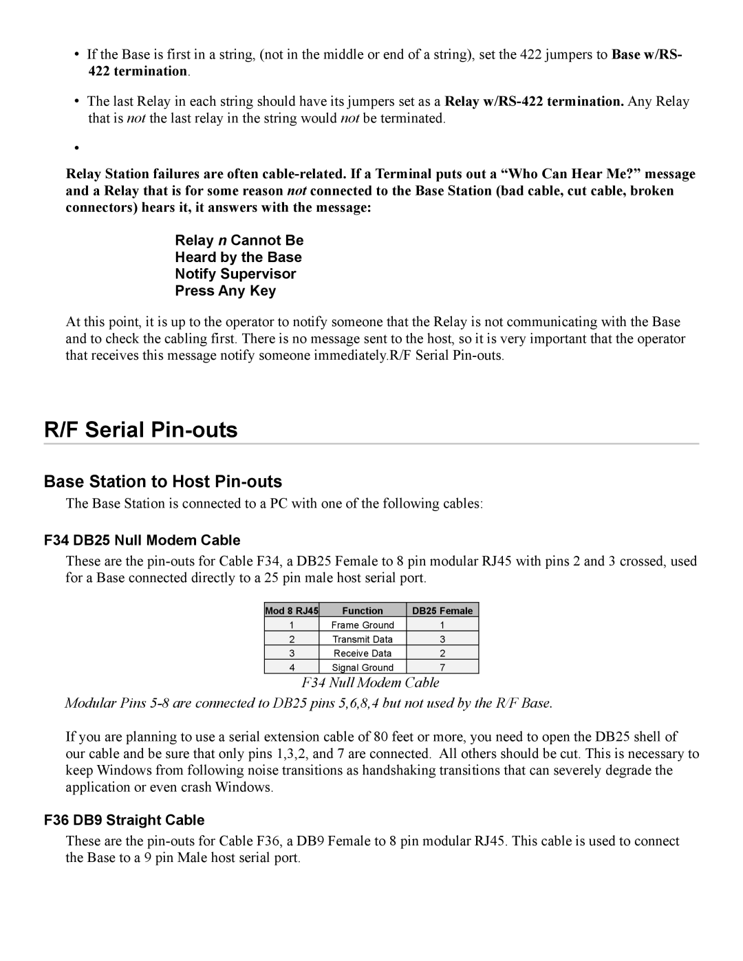
F34 DB25 Null Modem Cable
F36 DB9 Straight Cable
Firmware Upgrades
Terminal Firmware Upgrades
Relay Station RS422 Pin-outs
Normal Firmware Download for a Terminal
Code 39 Specifications
Base Station Firmware upgrades
Failsafe Firmware Download for a Terminal
C39
Code 39 Advanced Features and Functions
Mod 43 Check Character
Mod 43 Check character calculation for Code
Value 22 is the Check Character
Accumulate Mode
Full Ascii Extension to Code
Code 93 Specifications
Clear Enter
Codabar Specifications
Code 128 Specifications
A12345b
Codabar start/stop transmission
Interleaved 2 of 5 Code Specifications
UCC-128 Shipping Container Code
UPC / EAN Specifications
Isbn Specifications
Supplemental codes
UPC/EAN checksum character
MSI/Plessey Specifications
How to scan a bar code
Laser Scanners
Laser Options
Aiming the Laser Dot
Ascii Code Equivalent Table
BEL