Detailed Description
R
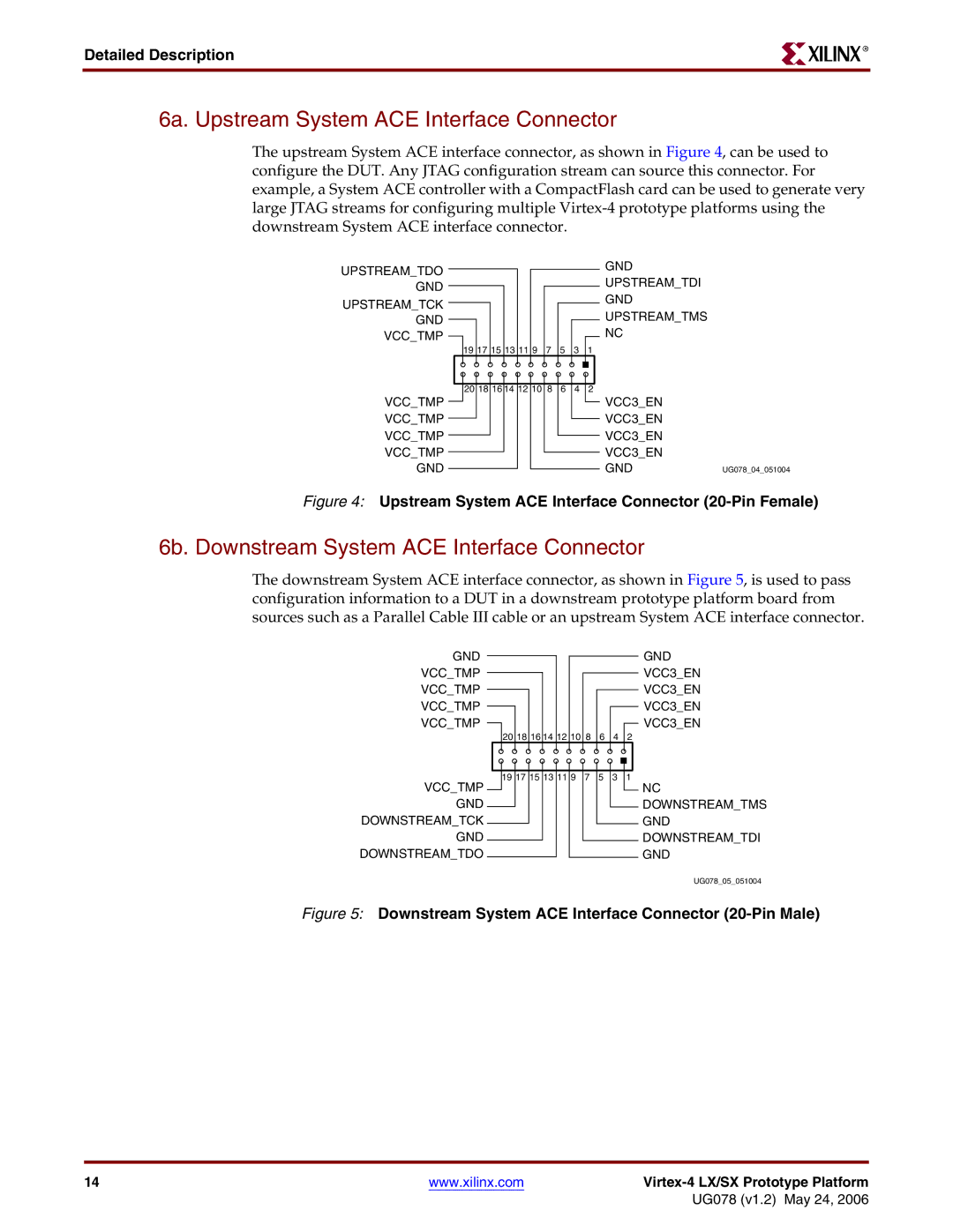
6a. Upstream System ACE Interface Connector
The upstream System ACE interface connector, as shown in Figure 4, can be used to configure the DUT. Any JTAG configuration stream can source this connector. For example, a System ACE controller with a CompactFlash card can be used to generate very large JTAG streams for configuring multiple
UPSTREAM_TDO
GND
UPSTREAM_TCK
GND
VCC_TMP ![]()
19 17 15 13 11 9
7
5
3
1
GND UPSTREAM_TDI GND UPSTREAM_TMS NC
VCC_TMP VCC_TMP VCC_TMP VCC_TMP GND
20 18 16 14 12 10 8
6
4
2
VCC3_EN
VCC3_EN
VCC3_EN
VCC3_EN
GND | UG078_04_051004 |
Figure 4: Upstream System ACE Interface Connector (20-Pin Female)
6b. Downstream System ACE Interface Connector
The downstream System ACE interface connector, as shown in Figure 5, is used to pass configuration information to a DUT in a downstream prototype platform board from sources such as a Parallel Cable III cable or an upstream System ACE interface connector.
GND
VCC_TMP
VCC_TMP
VCC_TMP
VCC_TMP
VCC_TMP GND DOWNSTREAM_TCK GND DOWNSTREAM_TDO
GND
VCC3_EN
VCC3_EN
VCC3_EN
VCC3_EN
20 18 16 14 12 10 8 | 6 | 4 | 2 | |
19 17 15 13 11 9 | 7 | 5 | 3 | 1 |
NC
DOWNSTREAM_TMS
GND
DOWNSTREAM_TDI
GND
UG078_05_051004
Figure 5: Downstream System ACE Interface Connector (20-Pin Male)
14 | www.xilinx.com |
|
|
| UG078 (v1.2) May 24, 2006 |