Detailed Description
R
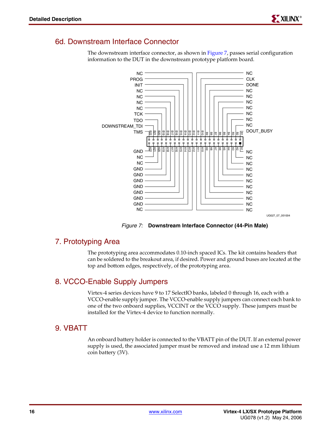
6d. Downstream Interface Connector
The downstream interface connector, as shown in Figure 7, passes serial configuration information to the DUT in the downstream prototype platform board.
NC PROG INIT NC NC NC NC TCK TDO
DOWNSTREAM_TDI TMS
GND
NC
NC
GND
GND
GND
GND
GND
GND
GND
NC
B22 | B21 | B20 | B19 | B18 | B17 | B16 | B15 | B14 | B13 | B12 | B11 | B10 | B9 | B8 | B7 | B6 | B5 | B4 | B3 | B2 | B1 |
A22 | A21 | A20 | A19 | A18 | A17 | A16 | A15 | A14 | A13 | A12 | A11 | A10 | A9 | A8 | A7 | A6 | A5 | A4 | A3 | A2 | A1 |
NC
CLK
DONE
NC
NC
NC
NC
NC
NC
NC
DOUT_BUSY
NC
NC
NC
NC
NC
NC
NC
NC
NC
NC
NC
UG027_07_051004
Figure 7: Downstream Interface Connector (44-Pin Male)
7. Prototyping Area
The prototyping area accommodates
8. VCCO-Enable Supply Jumpers
9. VBATT
An onboard battery holder is connected to the VBATT pin of the DUT. If an external power supply is used, the associated jumper must be removed and instead use a 12 mm lithium coin battery (3V).
16 | www.xilinx.com |
|
|
| UG078 (v1.2) May 24, 2006 |