R
Detailed Description
6c. Upstream Interface Connector
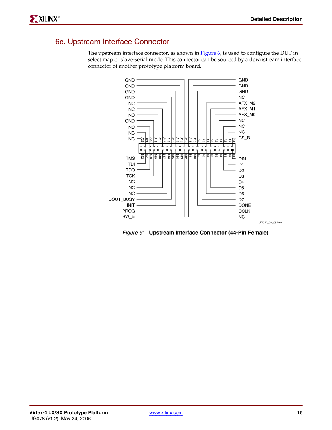
The upstream interface connector, as shown in Figure 6, is used to configure the DUT in select map or
GND
GND
GND
GND
NC
NC
NC
GND
NC
NC
NC
TMS
TDI
TDO
TCK
NC
NC
NC DOUT_BUSY INIT PROG RW_B
A22 | A21 | A20 | A19 | A18 | A17 | A16 | A15 | A14 | A13 | A12 | A11 | A10 | A9 | A8 | A7 | A6 | A5 | A4 | A3 | A2 | A1 |
B22 | B21 | B20 | B19 | B18 | B17 | B16 | B15 | B14 | B13 | B12 | B11 | B10 | B9 | B8 | B7 | B6 | B5 | B4 | B3 | B2 | B1 |
GND
GND
GND
NC
AFX_M2
AFX_M1
AFX_M0
NC
NC
NC
CS_B
DIN
D1
D2
D3
D4
D5
D6
D7
DONE
CCLK
NC
UG027_06_051004
Figure 6: Upstream Interface Connector (44-Pin Female)
| www.xilinx.com | 15 |
UG078 (v1.2) May 24, 2006
