MIC412TI and MIC412TF Camera Installation and Operation Manual
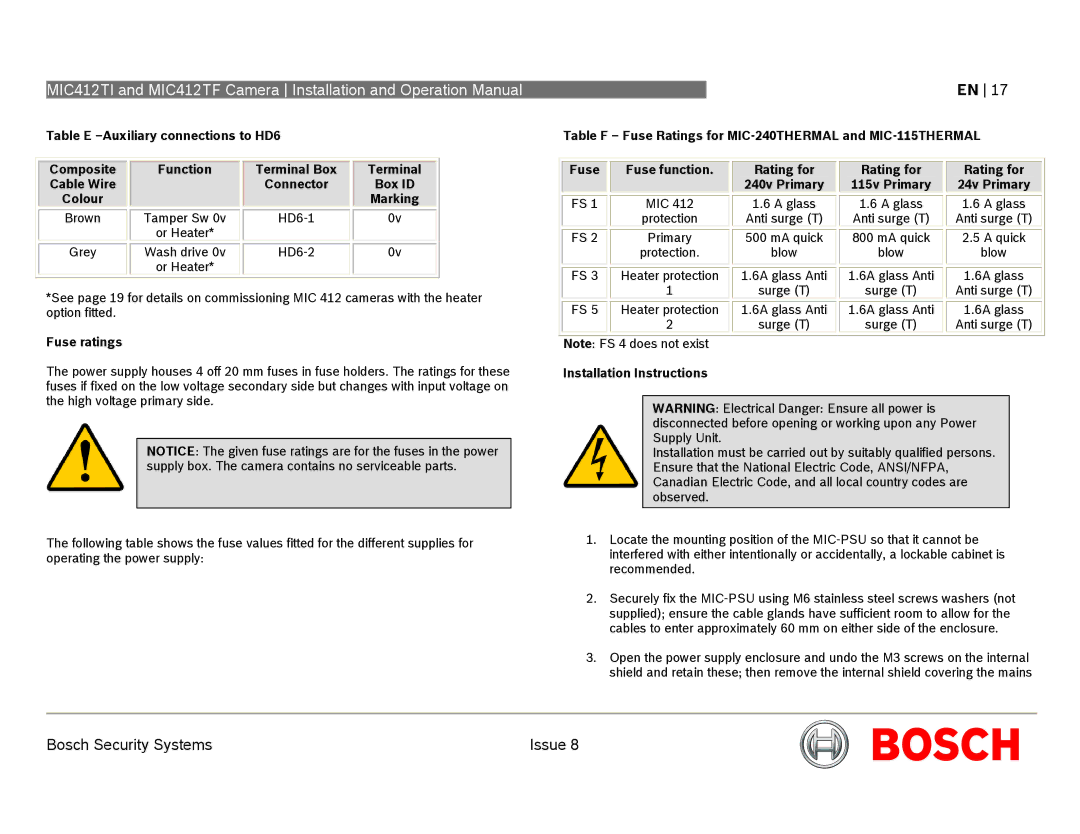
Table E
EN 17
Table F – Fuse Ratings for
Composite
Cable Wire
Colour
Brown
Grey
Function
Tamper Sw 0v
or Heater*
Wash drive 0v
or Heater*
Terminal Box
Connector
Terminal
Box ID
Marking
0v
0v
Fuse |
|
| Fuse function. |
|
|
| MIC 412 |
|
|
| |
FS 1 |
|
| |
|
|
| protection |
|
|
| Primary |
FS 2 |
|
| |
|
|
| protection. |
|
|
| Heater protection |
FS 3 |
|
|
Rating for
240v Primary
1.6A glass
Anti surge (T)
500 mA quick
blow
1.6A glass Anti
Rating for
115v Primary
1.6A glass
Anti surge (T)
800 mA quick
blow
1.6A glass Anti
Rating for
24v Primary
1.6A glass
Anti surge (T)
2.5A quick blow
1.6A glass
*See page 19 for details on commissioning MIC 412 cameras with the heater option fitted.
| 1 | |
|
| Heater protection |
FS 5 |
| |
|
| 2 |
surge (T)
1.6A glass Anti
surge (T)
surge (T)
1.6A glass Anti
surge (T)
Anti surge (T)
1.6A glass
Anti surge (T)
Fuse ratings
The power supply houses 4 off 20 mm fuses in fuse holders. The ratings for these fuses if fixed on the low voltage secondary side but changes with input voltage on the high voltage primary side.
NOTICE: The given fuse ratings are for the fuses in the power supply box. The camera contains no serviceable parts.
The following table shows the fuse values fitted for the different supplies for operating the power supply:
Note: FS 4 does not exist
Installation Instructions
WARNING: Electrical Danger: Ensure all power is disconnected before opening or working upon any Power Supply Unit.
Installation must be carried out by suitably qualified persons. Ensure that the National Electric Code, ANSI/NFPA, Canadian Electric Code, and all local country codes are observed.
1.Locate the mounting position of the
2.Securely fix the
3.Open the power supply enclosure and undo the M3 screws on the internal shield and retain these; then remove the internal shield covering the mains
Bosch Security Systems | Issue 8 |
