MIC412TI and MIC412TF Camera Installation and Operation Manual
CHAPTER 4 Configuring the MIC 412 Camera
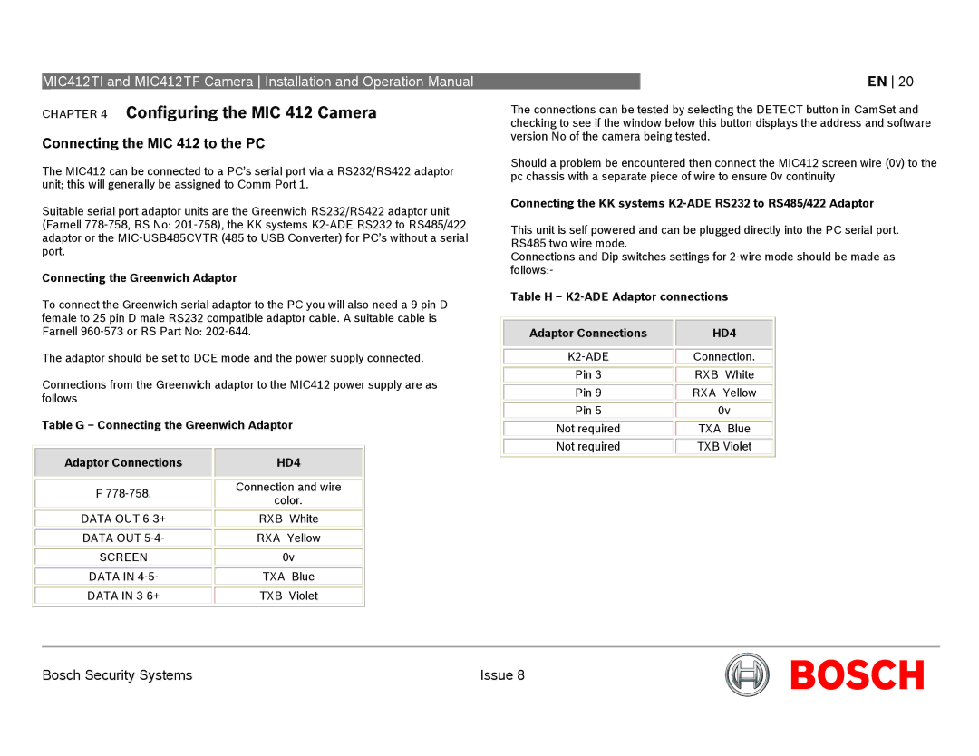
Connecting the MIC 412 to the PC
The MIC412 can be connected to a PC’s serial port via a RS232/RS422 adaptor unit; this will generally be assigned to Comm Port 1.
Suitable serial port adaptor units are the Greenwich RS232/RS422 adaptor unit (Farnell
Connecting the Greenwich Adaptor
To connect the Greenwich serial adaptor to the PC you will also need a 9 pin D female to 25 pin D male RS232 compatible adaptor cable. A suitable cable is Farnell
The adaptor should be set to DCE mode and the power supply connected.
Connections from the Greenwich adaptor to the MIC412 power supply are as follows
Table G – Connecting the Greenwich Adaptor
EN 20
The connections can be tested by selecting the DETECT button in CamSet and checking to see if the window below this button displays the address and software version No of the camera being tested.
Should a problem be encountered then connect the MIC412 screen wire (0v) to the pc chassis with a separate piece of wire to ensure 0v continuity
Connecting the KK systems K2-ADE RS232 to RS485/422 Adaptor
This unit is self powered and can be plugged directly into the PC serial port. RS485 two wire mode.
Connections and Dip switches settings for
Table H – K2-ADE Adaptor connections
Adaptor Connections |
| HD4 |
|
|
|
|
|
|
| Connection. | |
|
|
|
Pin 3 |
| RXB White |
|
|
|
Pin 9 |
| RXA Yellow |
|
|
|
Pin 5 |
| 0v |
|
|
|
Not required |
| TXA Blue |
|
|
|
Not required |
| TXB Violet |
Adaptor Connections
F
DATA OUT
DATA OUT
SCREEN
DATA IN
DATA IN
HD4
Connection and wire
color.
RXB White
RXA Yellow
0v
TXA Blue
TXB Violet
Bosch Security Systems | Issue 8 |