MIC412TI and MIC412TF Camera Installation and Operation Manual
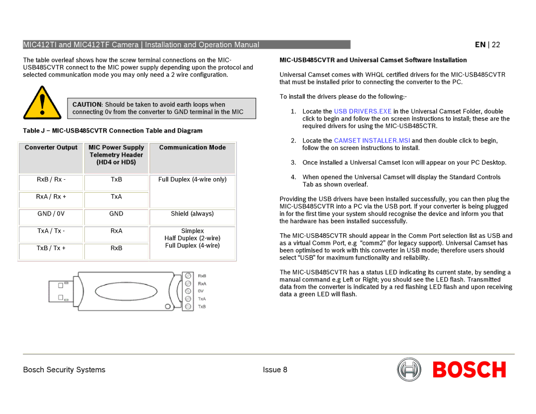
The table overleaf shows how the screw terminal connections on the MIC- USB485CVTR connect to the MIC power supply depending upon the protocol and selected communication mode you may only need a 2 wire configuration.
CAUTION: Should be taken to avoid earth loops when connecting 0v from the converter to GND terminal in the MIC
Table J –
|
|
|
|
|
|
|
|
|
|
|
| Converter Output |
|
| MIC Power Supply |
|
| Communication Mode |
|
|
|
|
|
| Telemetry Header |
|
|
|
|
|
|
|
|
| (HD4 or HD5) |
|
|
|
|
|
|
|
|
|
|
|
|
|
|
|
|
|
|
|
|
|
|
|
|
|
| RxB / Rx - |
|
| TxB |
|
| Full Duplex |
|
|
|
|
|
|
|
|
|
|
|
|
|
|
|
|
|
|
|
|
|
|
| RxA / Rx + |
|
| TxA |
|
|
|
|
|
|
|
|
|
|
|
|
|
|
|
|
|
|
|
|
|
|
|
|
|
| GND / 0V |
|
| GND |
|
| Shield (always) |
|
|
|
|
|
|
|
|
|
|
|
|
|
|
|
|
|
|
|
|
|
|
| TxA / Tx - |
|
| RxA |
|
| Simplex |
|
|
|
|
|
|
|
|
| Half Duplex |
|
|
|
|
|
|
|
|
| Full Duplex |
|
|
| TxB / Tx + |
|
| RxB |
|
|
| |
|
|
|
|
|
|
|
| ||
|
|
|
|
|
|
|
|
|
|
|
|
|
|
|
|
|
|
|
|
EN 22
MIC-USB485CVTR and Universal Camset Software Installation
Universal Camset comes with WHQL certified drivers for the
To install the drivers please do the following:-
1.Locate the USB DRIVERS.EXE in the Universal Camset Folder, double click to begin and follow the on screen instructions to install; these are the required drivers for using the
2.Locate the CAMSET INSTALLER.MSI and then double click to begin, follow the on screen instructions to install.
3.Once installed a Universal Camset Icon will appear on your PC Desktop.
4.When opened the Universal Camset will display the Standard Controls Tab as shown overleaf.
Providing the USB drivers have been installed successfully, you can then plug the
The
The
Bosch Security Systems | Issue 8 |