MIC412TI and MIC412TF Camera Installation and Operation Manual
3.Break the two wire links and remove any excess solder.
4.Solder the wire links using a soldering iron and TCW link wire from the left hand pads to the middle pads.
5.The power supply will now deliver +18vac to HD6.
6.Connect the heater wires (brown and gray) from the shielded composite cable to the HD6 terminal as labelled on the PCB.
7.The heaters are thermostatically controlled and will automatically turn on at +5°C (+41°F) and turn off at +15°C (+59°F).
8.Check all connections,
EN 19
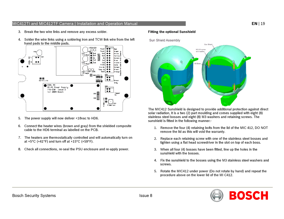
Fitting the optional Sunshield
The MIC412 Sunshield is designed to provide additional protection against direct solar radiation, it is a two (2) part moulding and comes supplied with eight (8) stainless steel bosses and eight (8) M3 washers and retaining screws. The sunshield is fitted in the following manner:-
1.Remove the four (4) retaining bolts from the lid of the MIC 412, DO NOT remove the lid as this will void the warranty.
2.Replace each retaining screw with one of the stainless steel bosses and tighten using a flat head screwdriver in the slot on top of each boss.
3.When all four (4) bosses have been fitted, line up the holes in the sunshield with the bosses.
4.Fix the sunshield to the bosses using the M3 stainless steel washers and screws.
5.Rotate the MIC412 under power (Do not rotate by hand) and repeat the procedure above on the lower lid of the MI C412.
Bosch Security Systems | Issue 8 |