MIC412TI and MIC412TF Camera Installation and Operation Manual
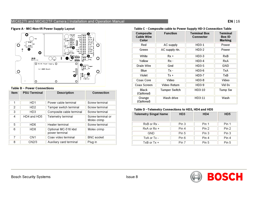
Figure A - MIC-Non-IR Power Supply Layout
Table B – Power Connections
|
|
|
|
|
|
|
|
|
| Item |
| PSU Terminal |
| Description |
| Connection |
|
|
|
|
|
|
|
|
|
|
|
|
|
|
|
|
|
|
|
| 1 |
| HD1 |
| Power cable terminal |
| Screw terminal |
|
|
|
|
|
|
|
|
|
|
| 2 |
| HD2 |
| Tamper switch terminal |
| Screw terminal |
|
|
|
|
|
|
|
|
|
|
| 3 |
| HD3 |
| Composite cable terminal |
| Screw terminal |
|
|
|
|
|
|
|
|
|
|
| 4 |
| HD4 and HD5 |
| Telemetry terminal |
| Screw terminal or |
|
|
|
|
|
|
|
| Molex crimp |
|
|
|
|
|
|
|
|
|
|
| 5 |
| HD6 |
| Heater terminal |
| Screw terminal |
|
|
|
|
|
|
|
|
|
|
| 6 |
| HD8 |
| Optional |
| Molex crimp |
|
|
|
|
|
| power terminal |
|
|
|
|
|
|
|
|
|
|
|
|
| 7 |
| CN1 |
| Coax video terminal |
| BNC socket |
|
|
|
|
|
|
|
|
|
|
| 8 |
| CN2/3 |
| Auxiliary card terminal |
| Plug in |
|
|
|
|
|
|
|
|
|
|
EN 16
Table C - Composite cable to Power Supply
|
|
|
|
|
|
|
|
|
| Composite |
| Function |
| Terminal Box |
| Terminal |
|
| Cable Wire |
|
|
| Connector |
| Box ID |
|
| Color |
|
|
|
|
| Marking |
|
|
|
|
|
|
|
|
|
|
| Red |
| AC supply |
|
| Power |
| |
|
|
|
|
|
|
|
|
|
| Green |
| AC supply rtn. |
|
| Power |
| |
|
|
|
|
|
|
|
|
|
|
|
|
|
|
|
|
|
|
| White |
| Rx + |
|
| RxB |
| |
|
|
|
|
|
|
|
|
|
| Yellow |
| Rx - |
|
| RxA |
| |
|
|
|
|
|
|
|
|
|
| Drain Wire |
| Gnd |
|
| GND |
| |
|
|
|
|
|
|
|
|
|
| Blue |
| Tx - |
|
| TxA |
| |
|
|
|
|
|
|
|
|
|
| Violet |
| Tx + |
|
| TxB |
| |
|
|
|
|
|
|
|
|
|
| Coax Core |
| Video |
|
| Video |
| |
|
|
|
|
|
|
|
|
|
| Coax Screen |
| Video Return |
|
| Vid 0v |
| |
|
|
|
|
|
|
|
|
|
| Black |
| Tamper Switch |
|
| Tamp Sw |
| |
| (Optional) |
|
|
|
|
|
|
|
|
|
|
|
|
|
|
|
|
| Orange |
| Wash drive |
|
| Wash |
| |
| (Optional) |
|
|
|
|
|
|
|
|
|
|
|
|
|
|
|
|
Table D –Telemetry Connections to HD3, HD4 and HD5
|
|
|
|
|
|
|
|
|
| Telemetry Singal Name |
| HD3 |
| HD4 |
| HD5 |
|
|
|
|
|
|
|
|
|
|
|
|
|
|
|
|
|
|
|
| RxB or Rx - |
| Pin 3 |
| Pin 1 |
| Pin 1 |
|
|
|
|
|
|
|
|
|
|
| RxA or Rx + |
| Pin 4 |
| Pin 2 |
| Pin 2 |
|
|
|
|
|
|
|
|
|
|
| GND |
| Pin 5 |
| Pin 3 |
| Pin 3 |
|
|
|
|
|
|
|
|
|
|
| TxA or Tx - |
| Pin 6 |
| Pin 4 |
| Pin 4 |
|
|
|
|
|
|
|
|
|
|
| TxB or Tx + |
| Pin 7 |
| Pin 5 |
| Pin 5 |
|
|
|
|
|
|
|
|
|
|
Bosch Security Systems | Issue 8 |