MIC412TI and MIC412TF Camera Installation and Operation Manual
4.cable terminal HD1. Removing this shield also gives access to the blanking plug to allow a suitable conduit or the cable gland to be fitted.
5.If using a conduit for the power cord, remove the blanking plug and install a suitable conduit in its place. Secure as recommended by the conduit manufacturer.
6.If using a power cord without a conduit, remove the blanking plug and fit the
7.Carefully connect the Live and Neutral cores to the correct HD1 screw terminals as shown below and also printed on the PCB.
|
|
|
|
| Live |
| |
|
|
|
|
| Neutral |
| |
|
|
|
|
| Earth |
| |
|
|
|
|
8.Crimp a 6 mm ring terminal (supplied) to the earth core on the power cord using copper washers. Securely bolt this to the earth termination post with the lid and PCB earth wires. Tighten the cable gland to secure and seal the power cord.
9.Reattach the mains
10.Feed the shielded composite cable through the metal M16 gland; then connect the shielded composite cable to the screw terminal HD3 as printed on the PCB. When completed tighten the cable gland to firmly grip the shielded cable.
11.Connect a tamper switch to HD2, if necessary.
12.Feed the coax cable through the cable gland and crimp the end with a BNC connector then connect the coax video cable to the CN1 socket.
EN 18
13.Use CN2 for additional
14.Crimp or screw telemetry connections to terminal HD4 or HD5 to connect the MIC camera to the control room.
15.When wiring is complete, apply power and check the all four (4) LEDs are lit.
•LED1 – 18 VAC power on to camera
•LED2 – 18 VAC power on to camera
•LED4 – Power on for optional heater
•LED5 – Power on for optional heater
16.
17.For installation of the
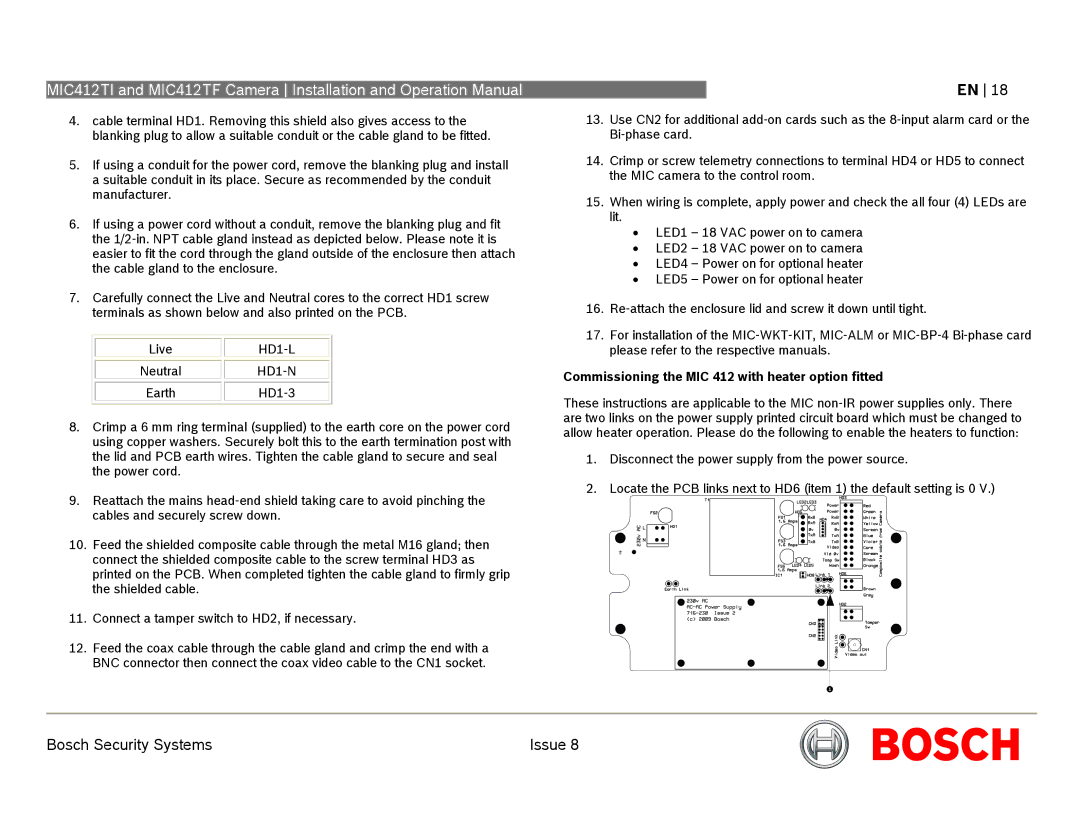
Commissioning the MIC 412 with heater option fitted
These instructions are applicable to the MIC
1.Disconnect the power supply from the power source.
2.Locate the PCB links next to HD6 (item 1) the default setting is 0 V.)
Bosch Security Systems | Issue 8 |