TABLE 20: STATIC RESISTANCES
|
|
|
|
|
| RESISTANCE, IWG |
|
|
|
| ||
DESCRIPTION |
|
|
|
|
|
|
|
|
|
| ||
|
|
|
|
| CFM |
|
|
|
| |||
|
|
|
|
|
|
|
|
|
|
|
|
|
|
| 1000 | 1200 | 1400 | 1600 |
| 1800 |
| 2000 | 2200 | 2400 | 2600 |
|
|
|
|
|
|
|
|
|
|
|
| |
ECONOMIZER1, 2 | 0.07 | 0.08 | 0.09 | 0.11 |
| 0.13 |
| 0.15 | 0.17 | 0.20 | 0.23 | |
ELECTRIC | 0.04 | 0.05 | 0.06 | 0.07 |
| 0.08 |
| 0.10 | 0.12 | 0.14 | 0.16 | |
HEATERS1 |
|
|
|
|
|
|
|
|
|
|
|
|
0.06 | 0.07 | 0.08 | 0.09 |
| 0.11 |
| 0.13 | 0.15 | 0.17 | 0.20 | ||
BOTTOM DUCT CONNECTIONS1 | 0.06 | 0.07 | 0.08 | 0.09 |
| 0.10 |
| 0.11 | 0.12 | 0.14 | 0.16 | |
1. Deduct these resistance values from the available external static pressure shown in SUPPLY AIR BLOWER PERFORMANCE Tables.
2. The pressure through the economizer is greater for 100% outdoor air than for 100% return air. If the resistance of the return air duct system is less than 0.25 IWG, the unit will deliver less CFM during full economizer operation.
PHASING | PROCEDUREFORADJUSTINGBELTTENSION: |
| |||
Check for proper compressor rotation. If the blower or |
| ||||
1 | Loosennu | (A)(topandbottom). |
| ||
compressors rotate in the wrong direction at | 2 | Adjustthet |
| byturningbolt(B). |
|
the electrical connection to the unit is misphased. | 3 | Neverloosennuts(C)fromeachother. |
| ||
4.Usebelttensioncheckertoapplyaperpendicularforcetobeonebeltatthe | |||||
Change the incoming line connection phasing to obtain |
| midpointofthespanasshown.Thedeflectionforceshouldbeapplied | |||
| untilaspecificdeflectiondistanceof4mm(5/32")is | .Todetermine | |||
proper rotation. (Scroll compressors operate in only |
| thedeflection | fromnormalposition,useastraight | dgefrom | |
| sheavetosheavedistanascereferenceline.herecommendedobtainedflectionforce | ||||
one direction. If the scroll is drawing low amperage, |
| isasfollows: |
| DEFLFORCE |
|
has similar suction and discharge pressures, or pro- |
|
|
|
| |
ducing a high noise level, the scroll is misphased). |
|
|
|
| |
(A) (C)**Never(B)Loosen Tnsionnewbeltsatthemax.deflectionbetweenforcerecomendminandeforthebelt
5.Afteradjusting,re-tightennuts(A).
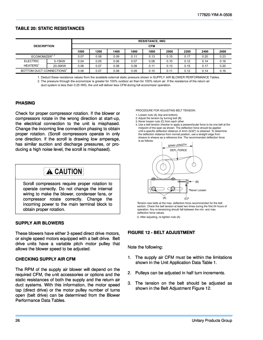
FIGURE 12 - BELT ADJUSTMENT
Note the following:
1. The supply air CFM must be within the limitations shown in the Unit Application Data Table 1.
2. Pulleys can be adjusted in half turn increments.
3. The tension on the belt should be adjusted as shown in the Belt Adjustment Figure 12.
Unitary Products Group
