MINIMUM POSITION ADJUSTMENT
With thermostat set to indoor fan on position, or termi- nals “R” to “G” energized, turn the Minimum Position
CONTROL | CONTROL POINT |
|
|
APPROX. 0F (0C) | 85 | 90 95 100 105 110 | |
CURVE | AT 50% RH | (29) | (32) (35) (38) (41) (43) |
|
A73 (23)
B | 70 (21) | 80 | |
(27) | |||
C | 67 (19) | ||
|
Adjusting screw (located on the damper control mod- ule) counterclockwise until the desired minimum damper position has been attained.
ENTHALPY SET POINT ADJUSTMENT
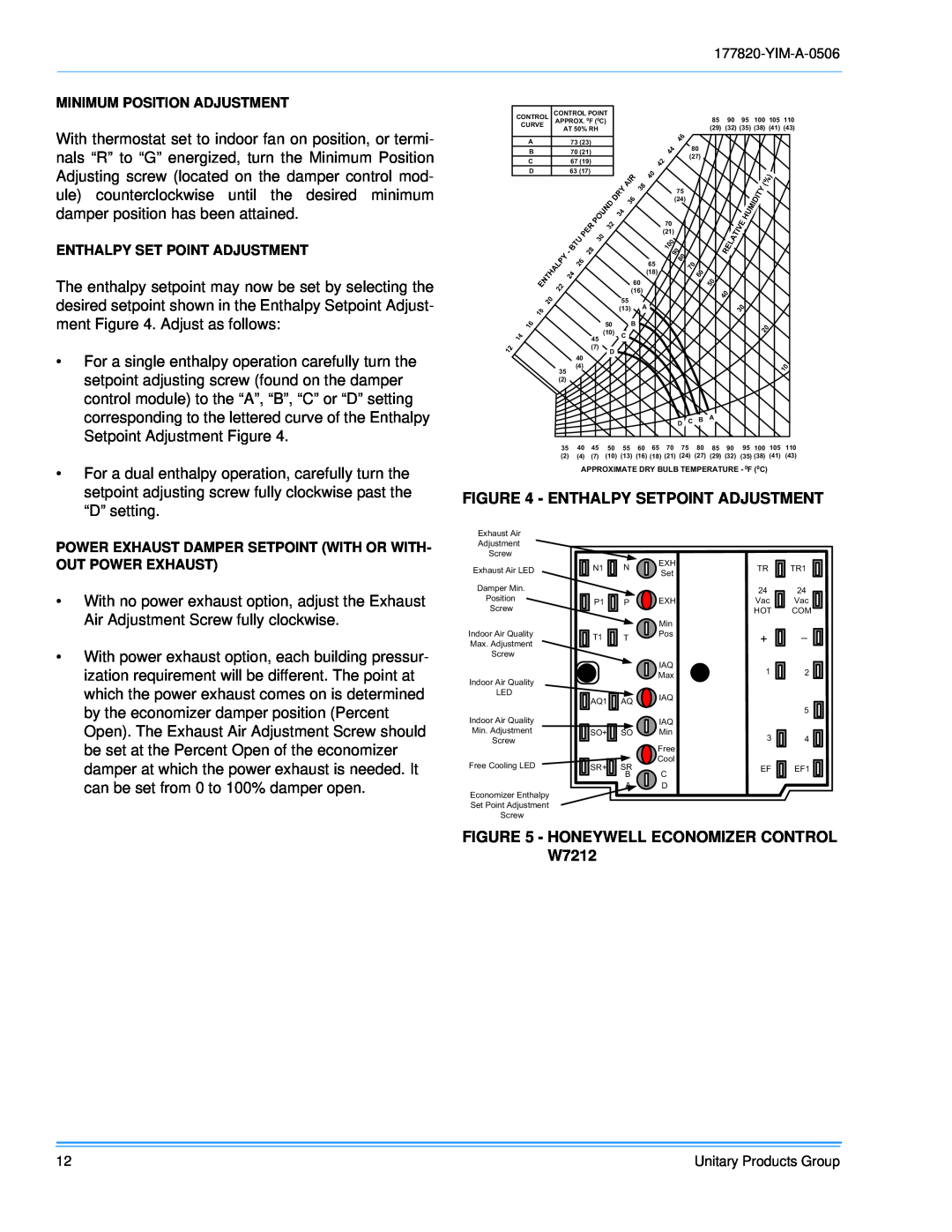
The enthalpy setpoint may now be set by selecting the desired setpoint shown in the Enthalpy Setpoint Adjust- ment Figure 4. Adjust as follows:
D63 (17)
45
75
(24)
70
(21)
65
(18)
60
(16)
55
(13)A
50 B
(10) C
•For a single enthalpy operation carefully turn the setpoint adjusting screw (found on the damper control module) to the “A”, “B”, “C” or “D” setting corresponding to the lettered curve of the Enthalpy Setpoint Adjustment Figure 4.
•For a dual enthalpy operation, carefully turn the setpoint adjusting screw fully clockwise past the “D” setting.
(7)
D
40
(4)
35
(2)
D C B A
35 40 45 50 55 60 65 70 75 80 85 90 95 100 105 110
(2)(4) (7) (10) (13) (16) (18) (21) (24) (27) (29) (32) (35) (38) (41) (43)
APPROXIMATE DRY BULB TEMPERATURE - 0F (0C)
FIGURE 4 - ENTHALPY SETPOINT ADJUSTMENT
POWER EXHAUST DAMPER SETPOINT (WITH OR WITH- OUT POWER EXHAUST)
•With no power exhaust option, adjust the Exhaust Air Adjustment Screw fully clockwise.
•With power exhaust option, each building pressur- ization requirement will be different. The point at which the power exhaust comes on is determined by the economizer damper position (Percent Open). The Exhaust Air Adjustment Screw should be set at the Percent Open of the economizer damper at which the power exhaust is needed. It can be set from 0 to 100% damper open.
Exhaust Air
Adjustment
Screw
Exhaust Air LED
Damper Min.
Position
Screw
Indoor Air Quality
Max. Adjustment
Screw
Indoor Air Quality
LED
Indoor Air Quality
Min. Adjustment
Screw
Free Cooling LED
Economizer Enthalpy
Set Point Adjustment
Screw
N1 | N | EXH | |
Set | |||
|
| ||
P1 | P | EXH | |
|
| Min | |
T1 | T | Pos | |
| |||
|
| IAQ | |
|
| Max | |
AQ1 | AQ | IAQ | |
| |||
|
| IAQ | |
SO+ | SO | Min |
|
| Free |
|
| Cool |
SR+ | SR |
|
| B | C |
| A | D |
TR ![]()
![]()
![]()
![]() TR1
TR1
2424
Vac ![]() Vac
Vac ![]()
![]()
HOT COM
+ ![]()
![]()
![]()
![]()
1 |
| 2 | |
| |||
| 5 | ||
3 |
|
| 4 |
|
| ||
EF |
|
| EF1 |
|
| ||
|
| ||
|
|
|
|
|
|
|
|
FIGURE 5 - HONEYWELL ECONOMIZER CONTROL W7212
12 | Unitary Products Group |
