FORM
Exhaust Fan Data
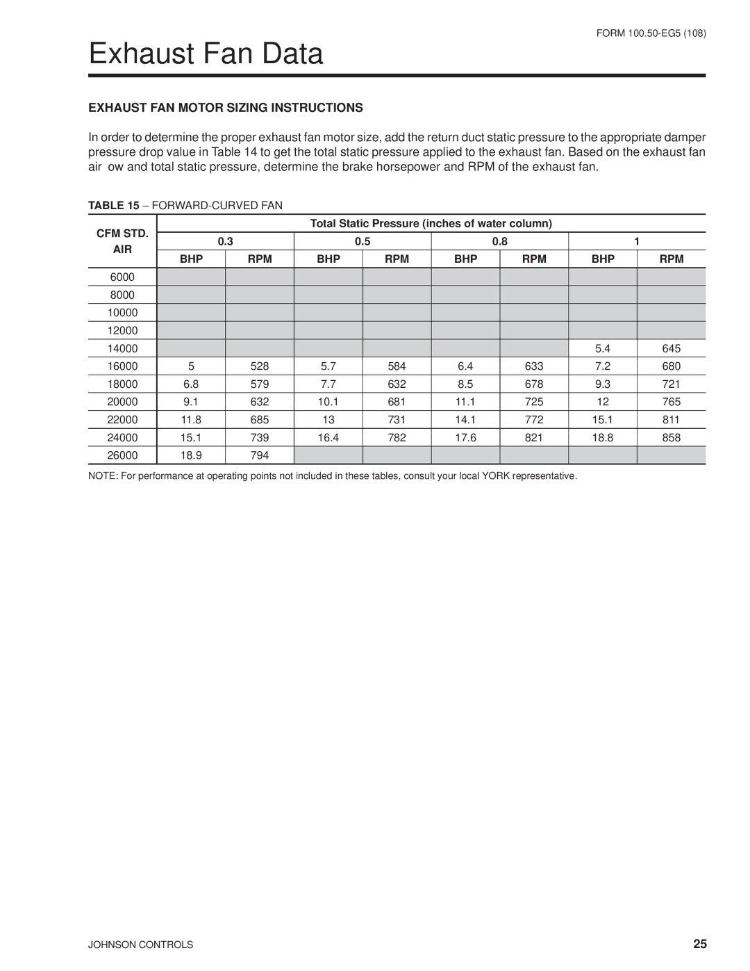
EXHAUST FAN MOTOR SIZING INSTRUCTIONS
In order to determine the proper exhaust fan motor size, add the return duct static pressure to the appropriate damper pressure drop value in Table 14 to get the total static pressure applied to the exhaust fan. Based on the exhaust fan airflow and total static pressure, determine the brake horsepower and RPM of the exhaust fan.
TABLE 15 –
CFM STD. |
|
|
| Total Static Pressure (inches of water column) |
|
|
| |||||
0.3 |
|
| 0.5 |
| 0.8 |
| 1 | |||||
AIR |
|
|
|
| ||||||||
BHP |
| RPM | BHP |
| RPM | BHP |
| RPM | BHP |
| RPM | |
|
|
|
|
| ||||||||
6000 |
|
|
|
|
|
|
|
|
|
|
|
|
8000 |
|
|
|
|
|
|
|
|
|
|
|
|
10000 |
|
|
|
|
|
|
|
|
|
|
|
|
12000 |
|
|
|
|
|
|
|
|
|
|
|
|
14000 |
|
|
|
|
|
|
|
|
| 5.4 |
| 645 |
16000 | 5 |
| 528 | 5.7 |
| 584 | 6.4 |
| 633 | 7.2 |
| 680 |
18000 | 6.8 |
| 579 | 7.7 |
| 632 | 8.5 |
| 678 | 9.3 |
| 721 |
20000 | 9.1 |
| 632 | 10.1 |
| 681 | 11.1 |
| 725 | 12 |
| 765 |
22000 | 11.8 |
| 685 | 13 |
| 731 | 14.1 |
| 772 | 15.1 |
| 811 |
24000 | 15.1 |
| 739 | 16.4 |
| 782 | 17.6 |
| 821 | 18.8 |
| 858 |
26000 | 18.9 |
| 794 |
|
|
|
|
|
|
|
|
|
NOTE: For performance at operating points not included in these tables, consult your local YORK representative.
JOHNSON CONTROLS | 25 |