JOHNSONCONTROLS |
| NOTES: |
|
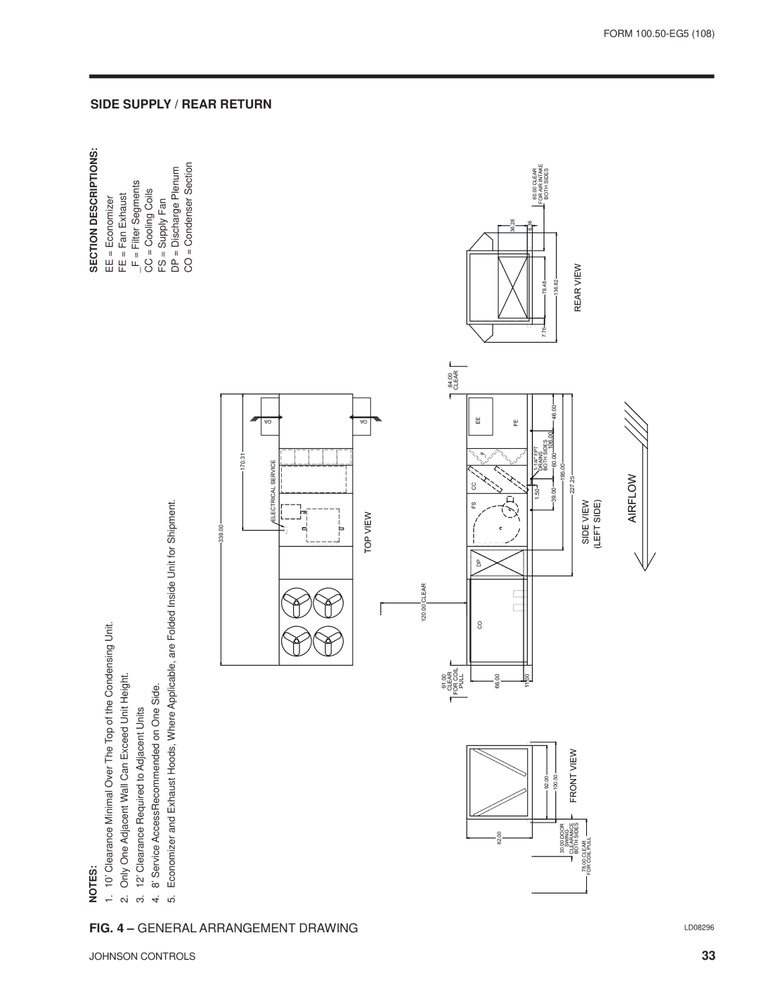
1. 10’ Clearance Minimal Over The Top of the Condensing Unit. |
| ||
|
| 2. Only One Adjacent Wall Can Exceed Unit Height. |
|
|
| 3. 12’ Clearance Required to Adjacent Units |
|
|
| 4. 8’ Service AccessRecommended on One Side. |
|
| ARRANGEMENT | 5. Economizer and Exhaust Hoods, Where Applicable, are Folded Inside Unit for Shipment. |
|
| 339.00 | OA | |
|
| 170.31 |
|
|
| ELECTRICAL SERVICE |
|
| DRAWING | TOP VIEW | OA |
|
| ||
|
|
|
120.00 CLEAR
SECTION DESCRIPTIONS:
EE= Economizer FE = Fan Exhaust _F = Filter Segments CC = Cooling Coils FS = Supply Fan
DP = Discharge Plenum CO = Condenser Section
SIDE SUPPLY / REAR RETURN
82.00
| 92.00 |
| 100.50 |
30.00 DOOR |
|
SWING | FRONT VIEW |
CLEARANCE | |
BOTH SIDES | |
78.00 CLEAR |
|
FOR COIL PULL |
|
91.00 |
|
CLEAR | 84.00 |
FOR COIL | CLEAR |
PULL |
|
| FS | CC |
|
| EE |
CO | DP |
| _F |
| |
|
|
|
|
| |
66.00 |
|
|
|
|
|
|
|
|
|
| FE |
11.00 |
|
|
|
|
|
|
| 1.50 |
| ||
|
|
| DRAINS |
|
|
|
|
| BOTH SIDES |
| |
| 39.00 | 60.00 | 106.00 | 46.00 | |
|
|
| 195.00 |
|
|
|
| 227.25 |
|
| |
SIDE VIEW (LEFT SIDE)
| 36.28 |
| 6.36 |
7.76 | 76.48 |
| 136.82 |
REAR VIEW
60.00 CLEAR
FOR AIR INTAKE
BOTH SIDES
AIRFLOW
33 | LD08296 |
FORM