34 | FIG | NOTES: |
|
|
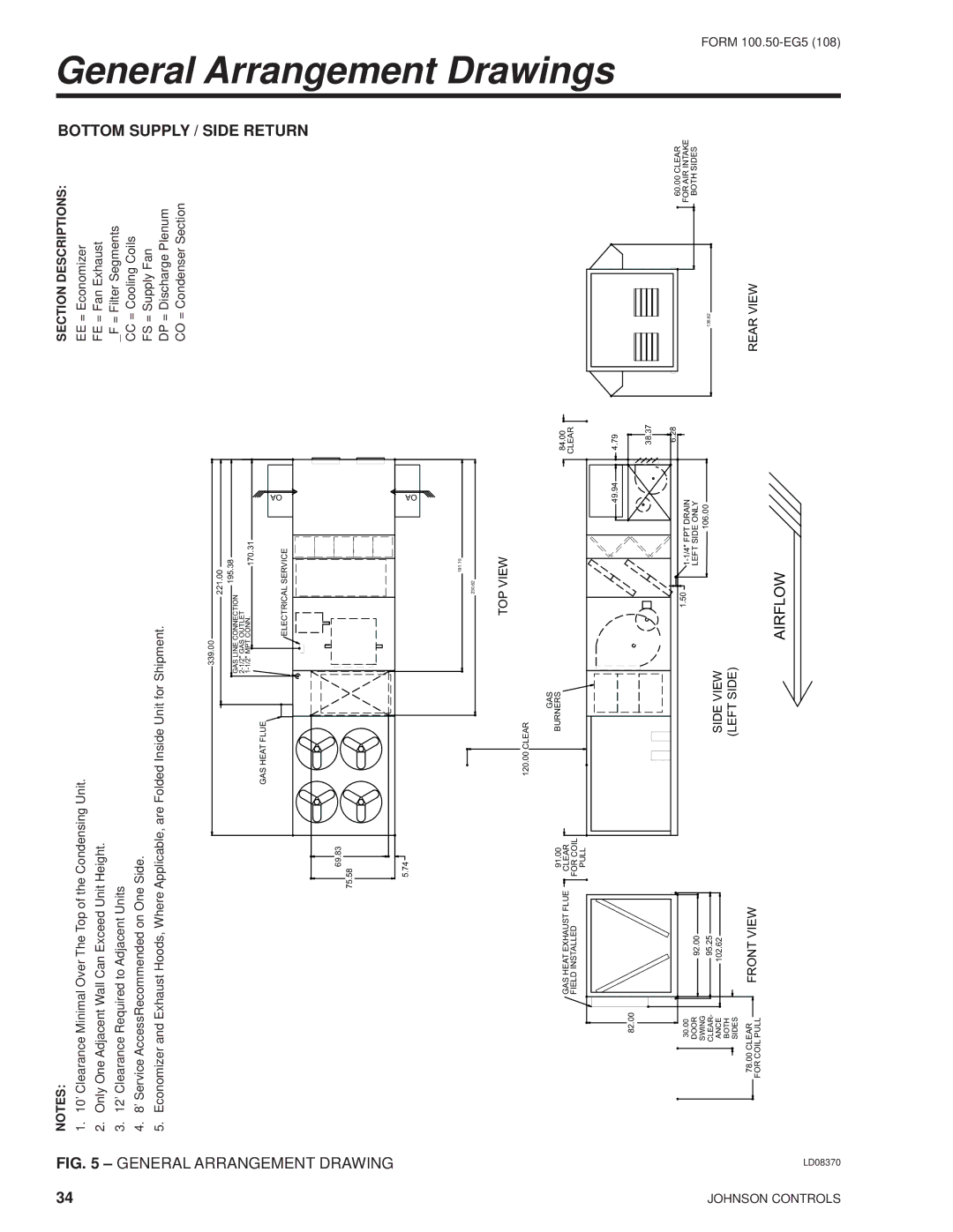
1. 10’ Clearance Minimal Over The Top of the Condensing Unit. |
|
| ||
| . |
|
| |
| 5 | 2. Only One Adjacent Wall Can Exceed Unit Height. |
|
|
| – |
|
| |
| 3. 12’ Clearance Required to Adjacent Units |
|
| |
| GENERAL |
|
| |
| 4. 8’ Service AccessRecommended on One Side. |
|
| |
| ARRANGEMENT | 5. Economizer and Exhaust Hoods, Where Applicable, are Folded Inside Unit for Shipment. |
|
|
| 339.00 | 221.00 | OA | |
|
|
|
| |
|
| GAS LINE CONNECTION | 195.38 |
|
|
|
|
| |
|
|
|
| |
|
| 170.31 |
| |
|
|
|
| |
|
| GAS HEAT FLUE |
|
|
| DRAWING | ELECTRICAL SERVICE |
| |
| 69.83 |
|
| |
|
| 75.58 |
|
|
|
| 5.74 |
| OA |
|
|
|
| |
|
|
| 191.19 |
|
|
|
| 230.62 |
|
SECTION DESCRIPTIONS: | BOTTOM |
EE = Economizer | |
FE = Fan Exhaust |
|
_F = Filter Segments |
|
CC = Cooling Coils | SUPPLY/SIDERETURN |
FS = Supply Fan | |
DP = Discharge Plenum |
|
CO = Condenser Section |
|
General Arrangement
JOHNSON CONTROLS | LD08370 |
82.00
30.00
DOOR
SWING CLEAR- ANCE BOTH SIDES
78.00CLEAR
FOR COIL PULL
|
|
|
| TOP VIEW | |
|
| 120.00 CLEAR |
|
| |
|
|
| GAS |
|
|
GAS HEAT EXHAUST FLUE | 91.00 |
| BURNERS |
| 84.00 |
CLEAR |
|
|
| CLEAR | |
FIELD INSTALLED | FOR COIL |
|
|
| |
|
|
|
| ||
| PULL |
|
|
|
|
|
|
|
|
| |
|
| 49.94 | 4.79 |
|
|
| 38.37 |
|
|
| 6.28 |
| 1.50 |
| |
|
|
| |
92.00 |
| LEFT SIDE ONLY |
|
95.25 | SIDE VIEW | 106.00 |
|
|
| ||
102.62 |
|
| |
| (LEFT SIDE) |
|
|
FRONT VIEW
AIRFLOW
60.00 CLEAR
FOR AIR INTAKE
BOTH SIDES
136.82
REAR VIEW
Drawings
FORM