FORM
Electrical Data
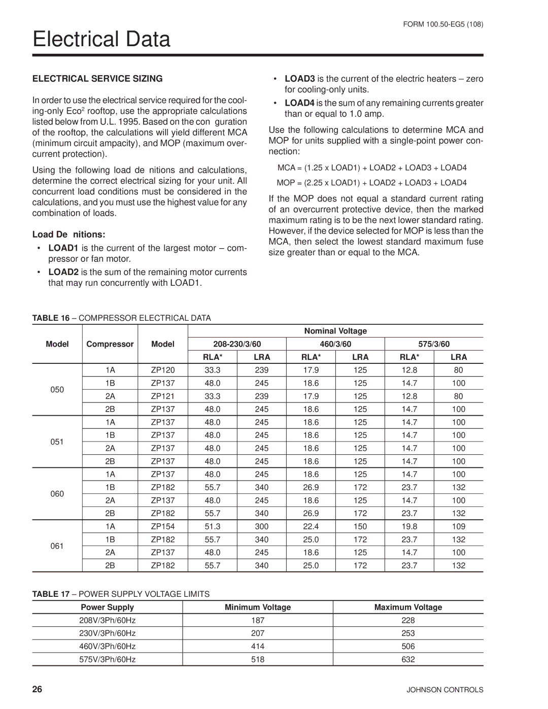
ELECTRICAL SERVICE SIZING
In order to use the electrical service required for the cool-
Using the following load definitions and calculations, determine the correct electrical sizing for your unit. All concurrent load conditions must be considered in the calculations, and you must use the highest value for any combination of loads.
Load Definitions:
•LOAD1 is the current of the largest motor – com- pressor or fan motor.
•LOAD2 is the sum of the remaining motor currents that may run concurrently with LOAD1.
TABLE 16 – COMPRESSOR ELECTRICAL DATA
•LOAD3 is the current of the electric heaters – zero for
•LOAD4 is the sum of any remaining currents greater than or equal to 1.0 amp.
Use the following calculations to determine MCA and MOP for units supplied with a
MCA = (1.25 x LOAD1) + LOAD2 + LOAD3 + LOAD4 MOP = (2.25 x LOAD1) + LOAD2 + LOAD3 + LOAD4
If the MOP does not equal a standard current rating of an overcurrent protective device, then the marked maximum rating is to be the next lower standard rating. However, if the device selected for MOP is less than the MCA, then select the lowest standard maximum fuse size greater than or equal to the MCA.
|
|
|
|
| Nominal Voltage |
|
|
| ||
Model | Compressor | Model | 460/3/60 |
| 575/3/60 |
| ||||
|
|
| RLA* | LRA | RLA* |
| LRA | RLA* |
| LRA |
| 1A | ZP120 | 33.3 | 239 | 17.9 |
| 125 | 12.8 |
| 80 |
050 | 1B | ZP137 | 48.0 | 245 | 18.6 |
| 125 | 14.7 |
| 100 |
2A | ZP121 | 33.3 | 239 | 17.9 |
| 125 | 12.8 |
| 80 | |
|
|
| ||||||||
| 2B | ZP137 | 48.0 | 245 | 18.6 |
| 125 | 14.7 |
| 100 |
| 1A | ZP137 | 48.0 | 245 | 18.6 |
| 125 | 14.7 |
| 100 |
051 | 1B | ZP137 | 48.0 | 245 | 18.6 |
| 125 | 14.7 |
| 100 |
2A | ZP137 | 48.0 | 245 | 18.6 |
| 125 | 14.7 |
| 100 | |
|
|
| ||||||||
| 2B | ZP137 | 48.0 | 245 | 18.6 |
| 125 | 14.7 |
| 100 |
| 1A | ZP137 | 48.0 | 245 | 18.6 |
| 125 | 14.7 |
| 100 |
060 | 1B | ZP182 | 55.7 | 340 | 26.9 |
| 172 | 23.7 |
| 132 |
2A | ZP137 | 48.0 | 245 | 18.6 |
| 125 | 14.7 |
| 100 | |
|
|
| ||||||||
| 2B | ZP182 | 55.7 | 340 | 26.9 |
| 172 | 23.7 |
| 132 |
| 1A | ZP154 | 51.3 | 300 | 22.4 |
| 150 | 19.8 |
| 109 |
061 | 1B | ZP182 | 55.7 | 340 | 25.0 |
| 172 | 23.7 |
| 132 |
2A | ZP137 | 48.0 | 245 | 18.6 |
| 125 | 14.7 |
| 100 | |
|
|
| ||||||||
| 2B | ZP182 | 55.7 | 340 | 25.0 |
| 172 | 23.7 |
| 132 |
TABLE 17 – POWER SUPPLY VOLTAGE LIMITS
Power Supply | Minimum Voltage | Maximum Voltage |
208V/3Ph/60Hz | 187 | 228 |
230V/3Ph/60Hz | 207 | 253 |
460V/3Ph/60Hz | 414 | 506 |
575V/3Ph/60Hz | 518 | 632 |
26 | JOHNSON CONTROLS |