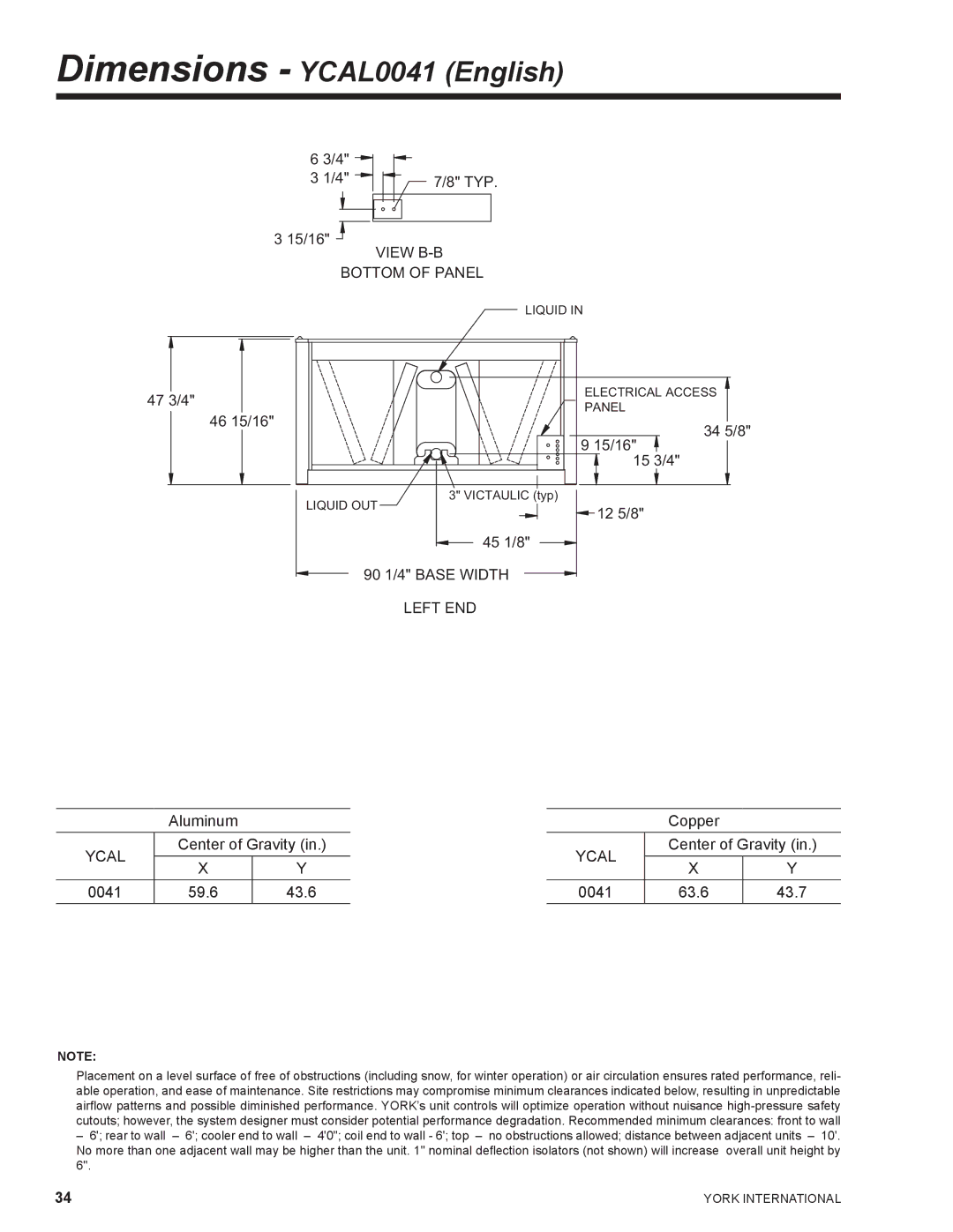
Dimensions - YCAL0041 (English)
6 3/4" |
|
3 1/4" | 7/8" TYP. |
|
3 15/16"
VIEW B-B
BOTTOM OF PANEL
LIQUID IN
47 3/4" |
|
| ELECTRICAL ACCESS |
|
| PANEL | |
|
|
| |
| 46 15/16" |
| 34 5/8" |
|
|
| |
|
|
| 9 15/16" |
|
|
| 15 3/4" |
|
| LIQUID OUT | 3" VICTAULIC (typ) |
|
| 12 5/8" | |
|
|
| |
|
|
| 45 1/8" |
90 1/4" BASE WIDTH
LEFT END
Aluminum
YCAL | Center of Gravity (in.) | ||
X | Y | ||
| |||
0041 | 59.6 | 43.6 | |
| Copper |
| |
YCAL | Center of Gravity (in.) | ||
X | Y | ||
| |||
0041 | 63.6 | 43.7 | |
NOTE:
Placement on a level surface of free of obstructions (including snow, for winter operation) or air circulation ensures rated performance, reli- able operation, and ease of maintenance. Site restrictions may compromise minimum clearances indicated below, resulting in unpredictable airflow patterns and possible diminished performance. YORK’s unit controls will optimize operation without nuisance
–6'; rear to wall – 6'; cooler end to wall – 4'0"; coil end to wall - 6'; top – no obstructions allowed; distance between adjacent units – 10'. No more than one adjacent wall may be higher than the unit. 1" nominal deflection isolators (not shown) will increase overall unit height by 6".
34 | YORK INTERNATIONAL |