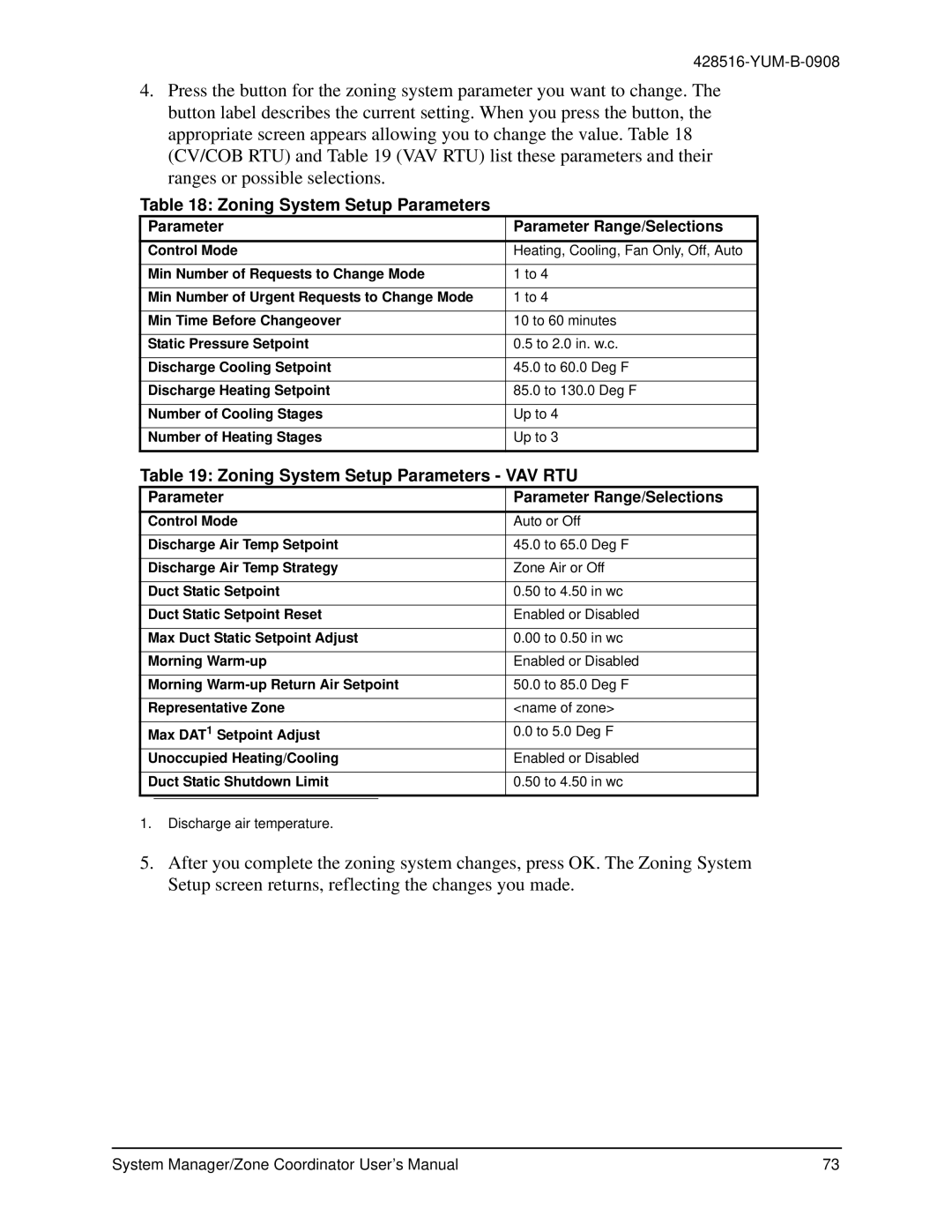
YK-ZCU2x0-0, YKSMU2x0-0, YK-ZCU4x0-0 specifications
York YK chillers are known for their reliability, efficiency, and advanced technology, making them a popular choice for a wide range of commercial applications. Among the various models, the YK-ZCU4x0-0, YKSMU2x0-0, and YK-ZCU2x0-0 stand out for their innovative features and performance capabilities.The YK-ZCU4x0-0 is designed to offer maximum cooling capacity while maintaining energy efficiency. One of its main features is the variable speed drive technology, which allows for precise control of the compressor speed based on real-time cooling demands. This technology not only enhances energy savings but also reduces wear and tear on components, extending the unit's lifespan. Additionally, the YK-ZCU4x0-0 is equipped with advanced microchannel heat exchanger technology, enabling better heat transfer and smaller refrigerant charges, which contributes to its lower environmental impact.
The YKSMU2x0-0 model is particularly notable for its integrated controls and monitoring systems. This chiller comes with a user-friendly touch screen interface that allows operators to monitor performance metrics and make adjustments with ease. The model features an intelligent control system that optimizes operational efficiency by adapting to changing load conditions. Moreover, its robust design makes it suitable for diverse applications, from data centers to manufacturing facilities, where reliability is crucial.
Finally, the YK-ZCU2x0-0 emphasizes modular design, which allows for easy installation and scalability. Its compact footprint makes it suitable for spaces with limited installation area. This model also supports modular redundancy, ensuring that if one module experiences issues, others can take over without disruption to the cooling process. The combination of high-efficiency performance, modularity, and state-of-the-art features makes the YK-ZCU2x0-0 an attractive option for facility managers looking for dependable chillers.
In summary, the York YK-ZCU4x0-0, YKSMU2x0-0, and YK-ZCU2x0-0 chillers represent the forefront of cooling technology, offering advanced features that cater to energy efficiency, flexibility, and operational reliability. Whether needing a robust solution for cooling large industrial spaces or a more compact unit for specific applications, these models provide the versatility and performance required in today's demanding environments.
