Installation and Operating Guide Warranty
B l e o f c o n t e n t s Installer quick setup guide
Record the Model Number
Serial no
G E
Millbrook Drive Lincolnshire, IL 60069, USA. Phone
Important Safety Instructions
NEC National Electrical Code
Table of Contents
Setup Checklist
Installation/Connections Overview
Status LED flashes while the program is running
Ventilation
Monitor Ventilation
Ventilation / Installation Overview
Monitor/Integrator Box Wall Mounting System
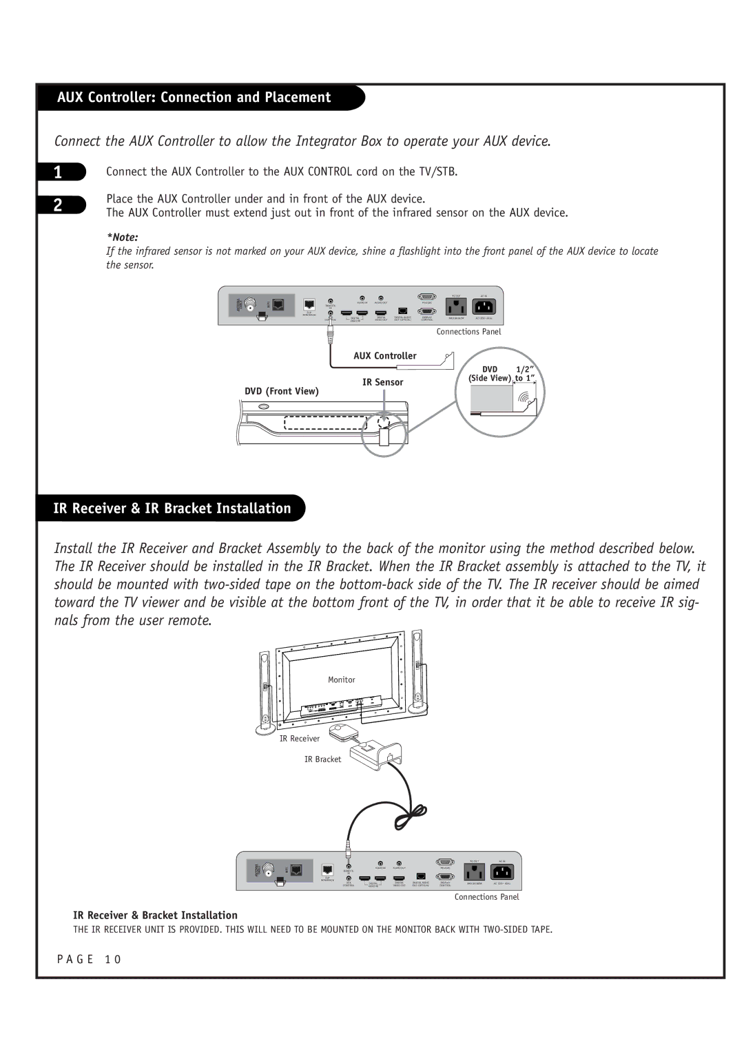
AUX Controller Connection and Placement
IR Receiver & IR Bracket Installation
G E 1
Antenna Hookup
Mini glossary
Cable Service Hookup
Connect cable service to the HD Integrator Box System
RS-232C Control Connections
Viewing Equipment Setup
Connect Aux Control IR Output as required of your system
DVI Hookup to RJP or DVD Player
Computer PC Hookup DVI
TV/Monitor RJP Connections
TV/Monitor
Audio Connection Digital Audio Optical Connections
On-Screen Menus Overview
Other Menus & On-Screen Displays
Info
User Remote Control Key Functions
G E 2
Mute
Installer Remote Control Key Functions
Number Keypad
Channel -/+
Auto Program Channel Search
Channel List
Channel List
Channel Control
Signal being received
Press the ADJ F or G button to adjust
OK Enter button
Clock Setup
On-Off Timers Setup
Time Zone options for your local area
Enter button
Use the ADJ D E F G buttons to set the Daylight Savings
See the next
Use the ADJ D or E button to highlight the Daylight Saving
Use the ADJ D or E button to highlight Time Zone and press
Use the ADJ F or G button to select the Time Zone
Press the OK Enter button
Minutes and time period to turn-on
You can set a time for the TV to automatically turn-on
Use the ADJ D E F G buttons to choose AM / PM, Hours
You can set a time for the TV to automatically turn-off
Use the ADJ D or E button to choose On or Off
Use the ADJ D or E button to highlight Auto Off and press
G E 3
Chip
OK Enter button
Use the ADJ D or E button to highlight Set Block Hour
Enter the 4 digits password
This option sets up hour that you wish to block
Use the ADJ D or E button to choose 1~12 hours and press
Options for Tvpg Rating
Use the ADJ D E F G buttons to choose and set up the menu
Description of the TV FCC Rating Codes
Description of the Mpaa and TV FCC Rating Codes
Options for Mpaa Rating
Use the ADJ D or E button to highlight the Mpaa Rating
Rating and press the OK Enter button
Enter the 4digits password
Use the ADJ D or E button to highlight the Can. English
Options for Can. English Rating
Options for Can. French Rating
Use the ADJ D or E button to highlight the Can. French
Canadian French Ratings E Expect No restriction. G For all
Use the ADJ D or E button to highlight the D/L Rating
Will be available only for digital channel signal
This function operates only when TV has received
Dim3 and press the OK Enter button
To highlight the Caption menu and press the OK Enter
When finished, press Menu repeatedly to remove
Caption Menu
Press OK Enter button
Customize the digital captions that appear on your screen
Use the ADJ D or E button to highlight Digital Mode
Use the ADJ D or E button to choose Service 1-Service
Use the ADJ D E F G buttons to customize each option Font
Use the ADJ D / E buttons to choose Dolby Digital or PCM
Sound Menu
Use the ADJ D or E button to highlight Digital Output
G E 4
To highlight the Sound menu and press the OK Enter
Use the ADJ D or E button to highlight Auto Volume
Use the ADJ D or E button to choose Mono, Stereo or SAP
Use the ADJ D or E button to choose English, Spanish or
French and press the OK Enter button
Language English, Español or Français
Language Control
Use the ADJ D or E button to highlight and set the Menu
Use the ADJ D or E button to highlight Menu Language
Set ID
Use the ADJ D or E button to choose 1-99 numbers and press
Color Temperature and press the OK Enter button
Picture Menu
Finished, press the Menu button
Buttons to set your own settings for the options. When
Use the ADJ D or E button to choose a preset screen
Use the ADJ D or E button to choose Screen Format
Use the ADJ D or E button to choose Film Mode and press
Use the ADJ D or E button to choose Noise Reduction
Typical Installer Menu
Commercial Mode Setup
G E 5
Cloning Connections/Learning Setup
Turn to the next page to continue Cloning Setup
If batteries are removed, the Clone Clock time will be lost
Learn Setup from Master TV/STB
Clone Programmer Learning Setup
Set the Clock Optional
Teach Master TV/STB’s Setup to the target
Cloning Connections / Teaching Setup
Disconnect TV/STB Power for 15 Seconds
Using the Installer’s Menu
Installer Menu
Accessing the Installer’s Menu
Installer Menu Items 000 through
Installer Menu Items 035 through
Detailed Descriptions of Installer Menu Items
Installer Sequence
Caption Lock
Mute Disable
Sleep Timer
Poll Rate
AUX Status
RJP Available
Start Minor Channel
Atsc Tune Mode
Atsc Band
VID OUT Format
Channel Picture Sound Setup Caption
Reference TV Features / Menus that can be Cloned
Film Mode
Changing/Adding Channel Labels on Master TV
Adding Channel Icons and Labels in the 2-5-4 + Menu Mode
To Do Channel Editing/Labeling, proceed as follows
Changing Source Labels on Master TV
Reference Detailed Information For Making a Master TV
Detailed Instructions
Procedure to Check Software Version
Reference Software Version Check
TV/STB Aux Input Configuration
TV/STB Aux Input Configuration
Type of Connector D-Sub 9-Pin Female
TV/STB RS-232 Monitor Requirements / RS-232 Troubleshooting
Displays ‘No Signal’ message at Power Off
Communication Parameter
Connecting the cable
RS-232C Control
Transmission / Receiving Protocol
Mc Set ID DataCr Data Key code Refer to page A18
KeyCommand m c
To send IR remote key code
Set ID OKDatax
Troubleshooting
Reset Clone After Static Shock
Reference Cloning Procedure Troubleshooting
Clone Programmer Troubleshooting
Troubleshooting Flow Chart
Installer Quick Setup Guide
G E 7
Glossary of Terms
OHM RF Cable
LG’S Responsibility
For Customer Support/Service Please call
Copyright 2008 LG Electronics U.S.A., Inc
OWNER’S Responsibility