Wiring for RS-232 Over Fiber and Alarm Communication
The
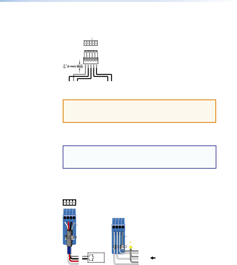
OVER FIBER ALARM
Tx Rx G | 1 | 2 |
| Tx Rx G |
| 1 2 |
|
Alarm Device | ||||
Figure 5. Wiring the RS-232 Over Fiber and Alarm Connector
ATTENTION: The length of exposed wires is critical. The ideal length is 3/16 inch (5 mm).
•Longer bare wires can short together.
•Shorter wires are not as secure in the connectors and could be pulled out.
For
The alarm pins do not produce any discrete on or off or voltage signals.
NOTES:
•The alarm port does not produce any discrete on or off voltage signals.
•If power is lost or if link 2 optical light is disconnected, lost, or broken, alarm pins 1 and 2 internally short.
Wiring for Remote Contact Closure Communication
Each port senses an external switch or contact closure. Use these ports to select an input on the switcher. Wire the connector as shown in figure 6 below.
CONTACT |
1 2 3 G |
Heat |
Shrink |
Over |
Shield |
Wires |
G | Switch | |
3 | ||
|
2
1
Ground
![]() Wire Nut
Wire Nut
Device 3
(Switches,
Device 2 relays, or similar items)
Device 1
Figure 6. Wiring the Contact Closure Connector
FOX T USW 103 Universal Switcher • Installation | 8 |