Casio AX200 manual U D a t a T r a n s f e r U n i t, Connecting the DTU

Page 103

www.axxessid.com

Installation & User Guide

from the sensor, then add one to whatever the value of Gain is at that moment. For example if the sensor starts detecting the mains at Gain = 33, then the suitable sensitivity would be Gain = 34. If “Alarm on off” is ticked in the sensor’s settings; once the mains in the cable is lost; an alarm transaction will appear on the main screen stating the date & time and the type of the alarm. All the alarms and routine readings can be observed in the Reports section.

D T U ( D a t a T r a n s f e r U n i t )

Originally introduced as an AX100 component, the data transfer unit is available as an option, to transfer database changes from the PC to the controller without the need for a direct PC connection.

After the initial programming, the AX100 controller can be disconnected from the PC and the controller will perform all access control functions autonomously. The controller can open and close doors without computer intervention.

The PC is where all the system configuration and data management is stored. The optional data transfer unit (DTU) enables the data that has been entered at the PC to be downloaded to the controller without the need of a physical PC connection.

One data transfer unit can be used for up to 255 controllers, or a total of 16,000 cardholders distributed over multiple controllers in a single download. E.g. 10 controllers each with 1,600 cardholders can be downloaded in one go, without the need to go backwards and forwards between the PC and controller. Similarly 255 controllers each with 60 cardholders can be downloaded to each controller without returning to the PC. Only valid cardholders are downloaded to the controller.

The Data Transfer Unit is fully plug and play at the controller and PC. The AX200 PC software allows multiple DTU’s to be used.

Connecting the DTU

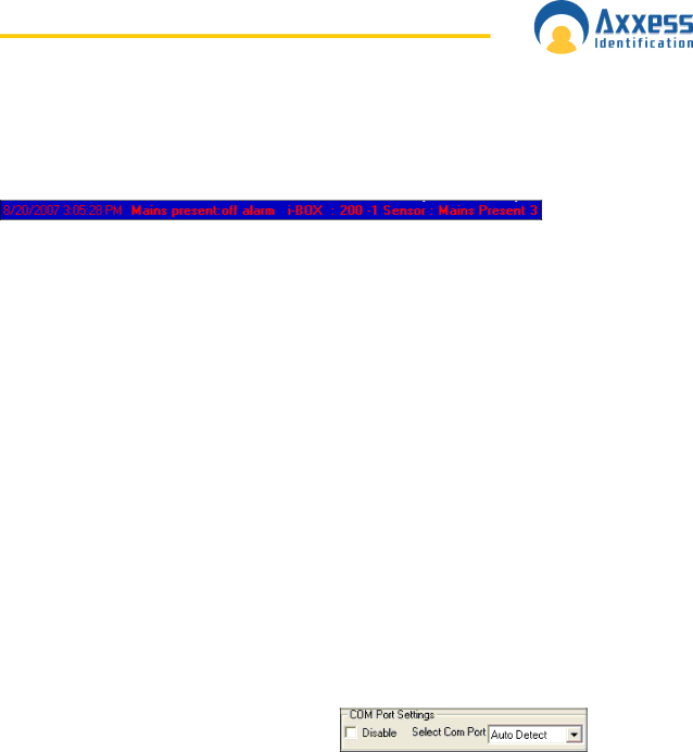
Make sure the COM port settings are enabled in System Settings • General Settings. Connect the power supply to the communication cable at the 15

way connector. Plug in the 9 way connector to the serial port of the PC. Start the AX200 software. Connect the DTU to the RJ45 connector, follow the on-screen instructions of the install wizard.

After configuring the DTU, the following window will appear on the screen. This window contains the list of the doors that require download.

AX200 Installation & User Guide – July 2007

1 0 3

Image 103
Contents AX200 & i-BOX Email info@axxessid.com C e n s e a g r e e m e n t N t e n t s Photo Photo ID Add a Photo Rollback 109 103105 108AX200 Software Setup 2 0 0 InstallationInstallation & User Guide Installation & User Guide IP Address D e f i n i t i o n s a p p l i c a b l e t o t h e a X 2 02 0 0 & i B O X C o n n e c t i o n s WAN ConfigurationSounder /Beacon for i-BOX IC-ASB AX200 Expander Board Connections Breakglass Wiring AX200 Break glass Wiring AX200AX50 / AX100 Break glass wiring AX50/AX100Installation & User Guide Installation & User Guide 2 0 0 S o f t w a r e F t w a r e InstallationOperating Systems Installation & User Guide Installation & User Guide A r t i n g t h e a X 2 0 0 S o f t w a r e Language Selection Password ReminderWindows Classic or Graphic Style XP Screen C k u p & R e s t o r e Email Backup Settings Standard Query Language SQL Communication between the AX200 Software and Controller Database Integrity CheckPlug & Play Devices N t r o l l e r S t a t u s & C o n t r o l High Security Mode HSMDate and Time Door Unlock ModeOn & Offline Operation Performance Analyzer Force Download & Clear ControllerTransaction Screen Who’s In/Out List Photo Display Display FiltersInstallation & User Guide Test Wizard Save on ExitInstallation & User Guide Installation & User Guide Installation & User Guide Installation & User Guide R d h o l d e r Main SettingsCard Number Department Access GroupImprint Number EmploymentInstallation & User Guide Photo ID PhotoCapture Picture from Camera Add a PhotoTemplates Import Picture from FileAdd New Card Wizard Card Replacement Wizard Card Diagnostics Search Database Fields per Cardholder Main Settings TabCard 0 Function Print Current Card DetailsOther Info Employer Mode Settings Extended Door Open Time Ext’d Door Set High Security Mode Set Hi SecPersonal Info High Security Hi SecVehicle info C e s s P o i n t C o n f i g u r a t i o n Access Point SettingsAccess Identity Access Point NameDoor Comments Door Contact Settings Start-up Mode SettingsDoor Release Time PIN Settings Hardware Version Device ParametersDevice Group Device TypeSerial Number in Batch Access GroupsFirmware Version Batch NumberDevice Manager Creating a new access groupAutomatic IP Setup Installation & User Guide Device Status Indication Installation & User Guide Device Settings Test Connection Fire alarmSite Info S t e m S e t t i n g sTest Wizard Mail Unknown Format to Axxess ID Mail FacilitiesCompact Database DB MaintenanceFirmware Settings Rollback Hidden FunctionsInstallation & User Guide General Settings COM Port Settings Function SettingsLink Alive Retry Times Multiple/Single Card Format Select COM PortR m a t & S t a t i s t i c s Default Access LevelDefault Time Zone DefaultFacility Code Card Type InformationC u r i t y S e t t i n g s Card Format Analyzer & Format ConfigurationCard Matching Adding a New Authorisation Group Adding a New UserP o r t Cardholder Brief Log File Cardholder DetailsDossier System Summary Work SpellOperators EnvironmentalFormat Types PrintingDestination Door Panel Position Sensor V i r o n m e n t BOX Parameters Sensor SettingsAlarms Shunt alarm on delay BOX SettingsAccumulation Period PDU Power Distribution UnitDetails Power feed group Normal Power switched on, power sensed LED on solid Hardware Connection Details SensorIsolate PIR Installation & User Guide Dust Particle Sensor Mains Present Sensor U D a t a T r a n s f e r U n i t Connecting the DTUInstallation & User Guide Add a New Door using a DTU DTU Step by Step Adding Card Formats using a DTUDTU Operation DTU LED IndicatorsClear DTU M o v i n g t h e a X 2 0 0 P r o g r a mT i V i r u s Installation & User Guide Fingerprint Reader A d e r sConfiguring Verid+ Programming a New User Getting Started Quickly Proximity Readers Installation & User Guide Output Type AXM ReadersProximity Request to Exit