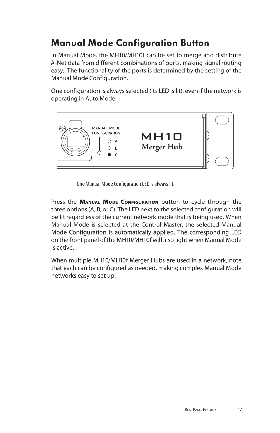
Aviom MH10m, MH10f manual Manual Mode, Configuration a Merge All

Page 28

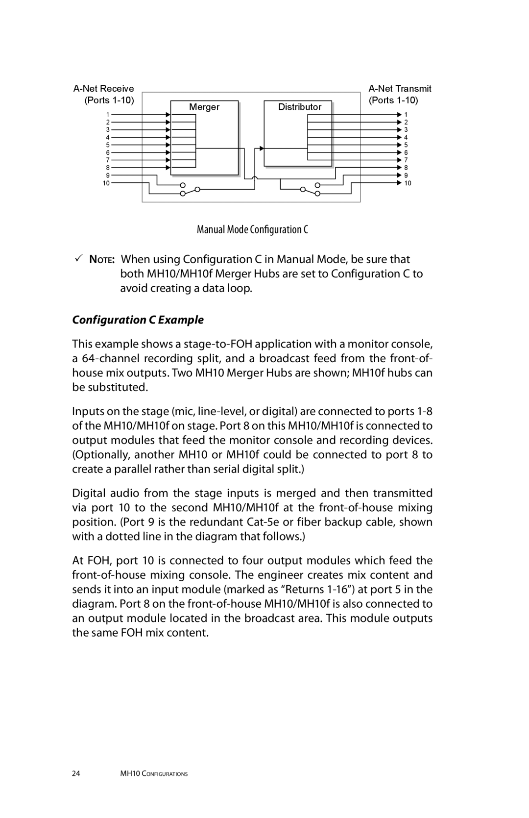
Manual Mode

Three signal routing configurations are available on each MH10/MH10f when the network is running in Manual Mode.

Configuration A (Merge All)

Manual Mode Configuration A (Merge All) functions similarly to Auto Mode. For digital splits and data copies, Manual Mode Configuration A is ideal.

Configuration B (Merge 1-9)

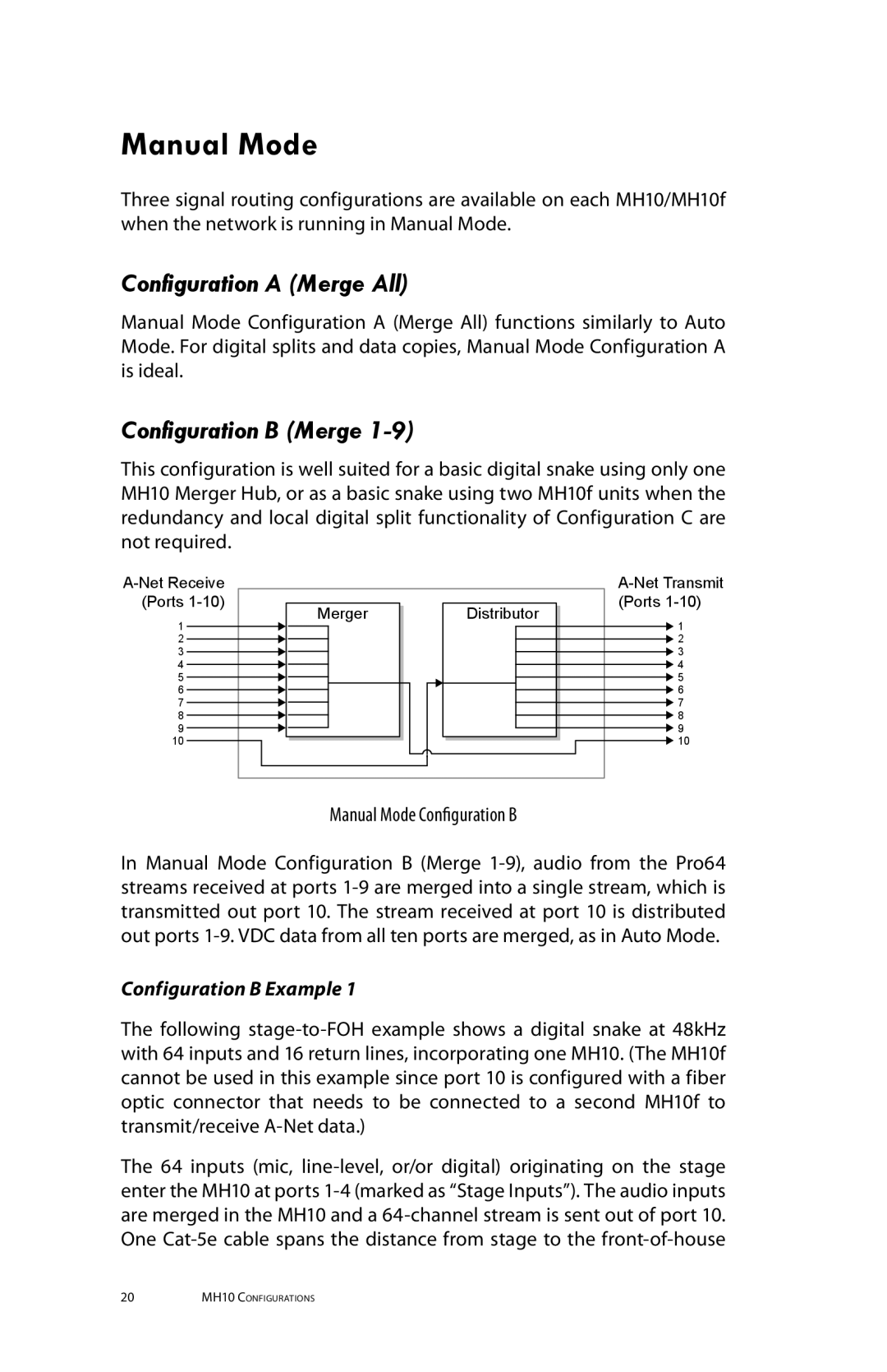
This configuration is well suited for a basic digital snake using only one MH10 Merger Hub, or as a basic snake using two MH10f units when the redundancy and local digital split functionality of Configuration C are not required.

A-Net Receive


A-Net Transmit

(Ports 1-10)

Merger

Distributor

(Ports 1-10)

1

1


2


2

3


3

4


4

5


5

6


6

7


7

8


8

9


9

10


10

Manual Mode Configuration B

In Manual Mode Configuration B (Merge 1-9), audio from the Pro64 streams received at ports 1-9 are merged into a single stream, which is transmitted out port 10. The stream received at port 10 is distributed out ports 1-9. VDC data from all ten ports are merged, as in Auto Mode.

Configuration B Example 1

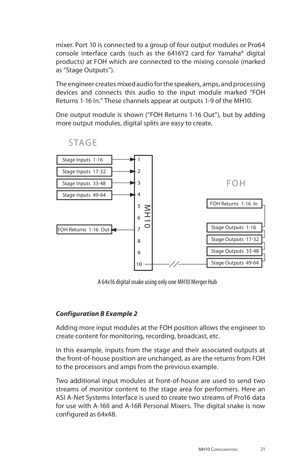
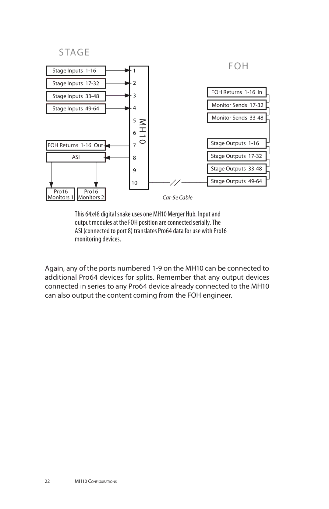
The following stage-to-FOH example shows a digital snake at 48kHz with 64 inputs and 16 return lines, incorporating one MH10. (The MH10f cannot be used in this example since port 10 is configured with a fiber optic connector that needs to be connected to a second MH10f to transmit/receive A-Net data.)

The 64 inputs (mic, line-level, or/or digital) originating on the stage enter the MH10 at ports 1-4 (marked as “Stage Inputs”). The audio inputs are merged in the MH10 and a 64-channel stream is sent out of port 10. One Cat-5e cable spans the distance from stage to the front-of-house

20MH10 Configurations
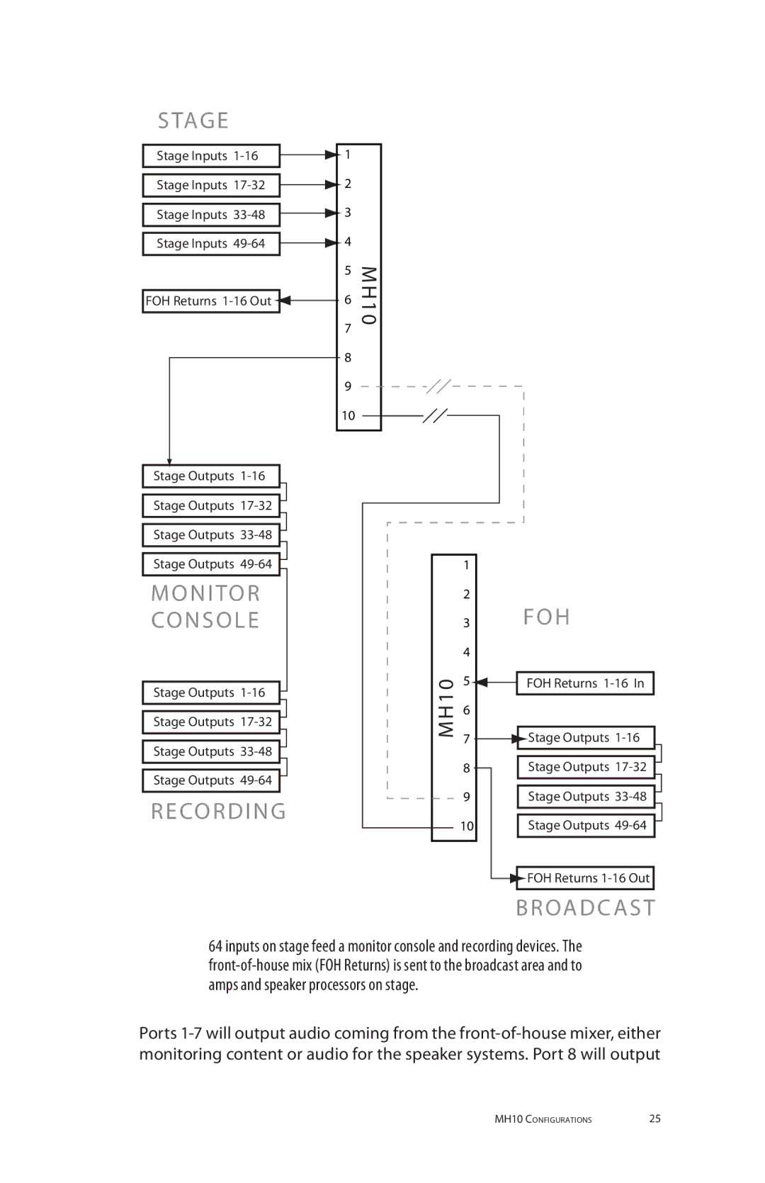
Image 28
Contents User Guide Certifications Iii Important Safety Instructions Warranty Information Aviom, Inc. Limited Warranty Table of Contents Viii EtherCon Connector FeaturesWelcome LC Connector SFP ModuleFirmware Update Cat-5eAbout A-Net Sample Rate Minimum MaximumControl Data ClockingNet Ports Support For Pro16 Series Products AC Line Conditioning AC PowerRack Mounting Cleaning VentilationFront Panel Components  MH10 Rear Panel MH10f Rear Panel  Front Panel Features Network Mode IndicatorNet Port LEDs Net LEDManaged Mode LED AC Power Rear Panel FeaturesBackup DC Power MH10f Net Ports Manual Mode Configuration Button MH10 Configurations Auto ModeR G E Manual Mode Configuration a Merge AllStage TAG E Configuration C Merge Configuration C Example Monitor Console MH10 Configuration Errors Data LoopsSpecifications Fiber Optic ModesDimensions Index SFP Port A, B. See A-Net Port See A-Net Ports