Sunrise Global CE4000, Cable Explorer TDR Module user manual Measurements

Page 30

Chapter 3

Measurements

31

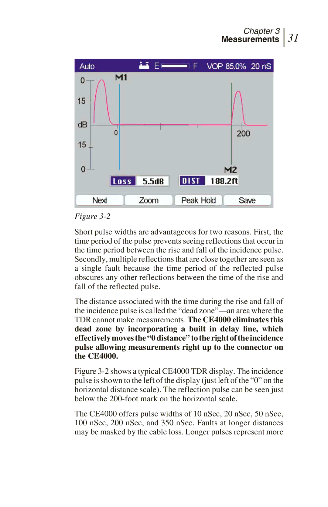
Figure 3-2

Short pulse widths are advantageous for two reasons. First, the time period of the pulse prevents seeing reflections that occur in the time period between the rise and fall of the incidence pulse. Secondly, multiple reflections that are close together are seen as a single fault because the time period of the reflected pulse obscures any other reflections between the time of the rise and fall of the reflected pulse.

The distance associated with the time during the rise and fall of the incidence pulse is called the “dead zone”—an area where the TDR cannot make measurements. The CE4000 eliminates this dead zone by incorporating a built in delay line, which effectively moves the “0 distance” to the right of the incidence pulse allowing measurements right up to the connector on the CE4000.

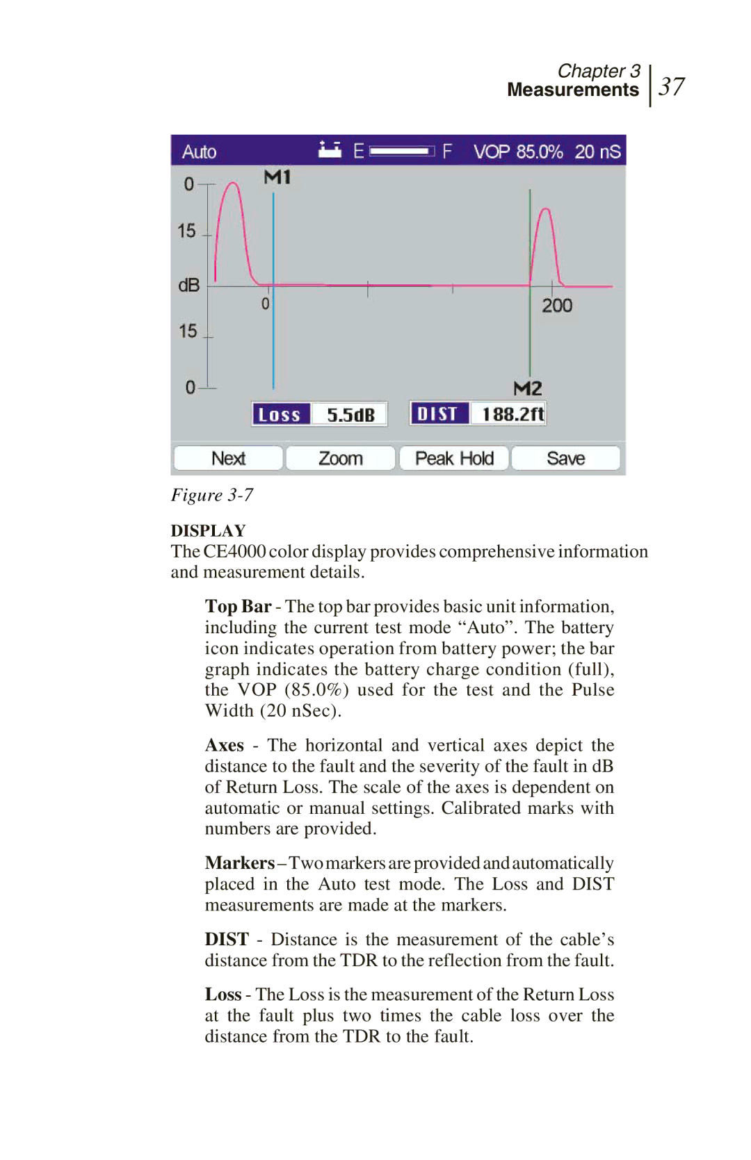
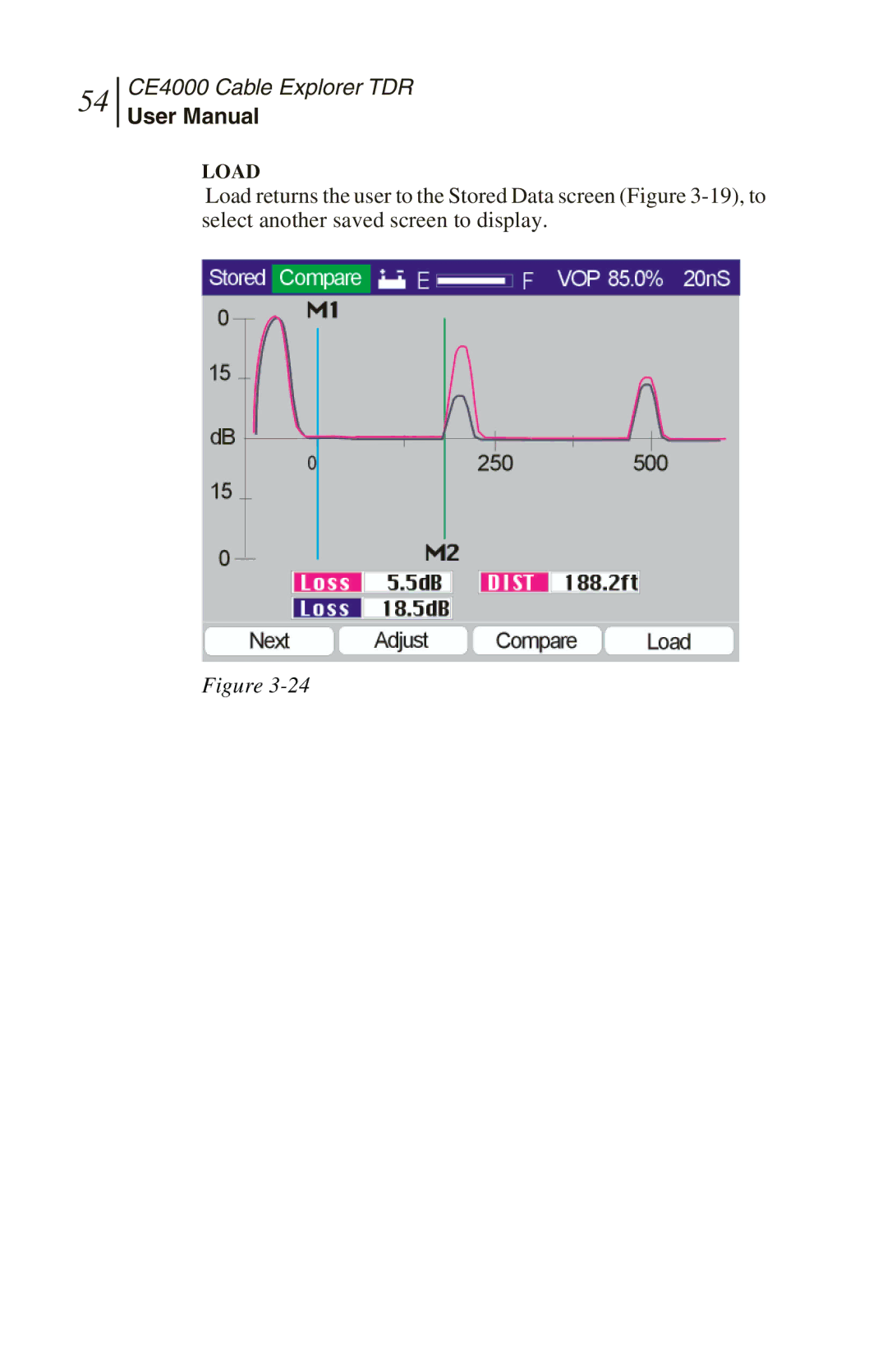
Figure 3-2 shows a typical CE4000 TDR display. The incidence pulse is shown to the left of the display (just left of the “0” on the horizontal distance scale). The reflection pulse can be seen just below the 200-foot mark on the horizontal scale.

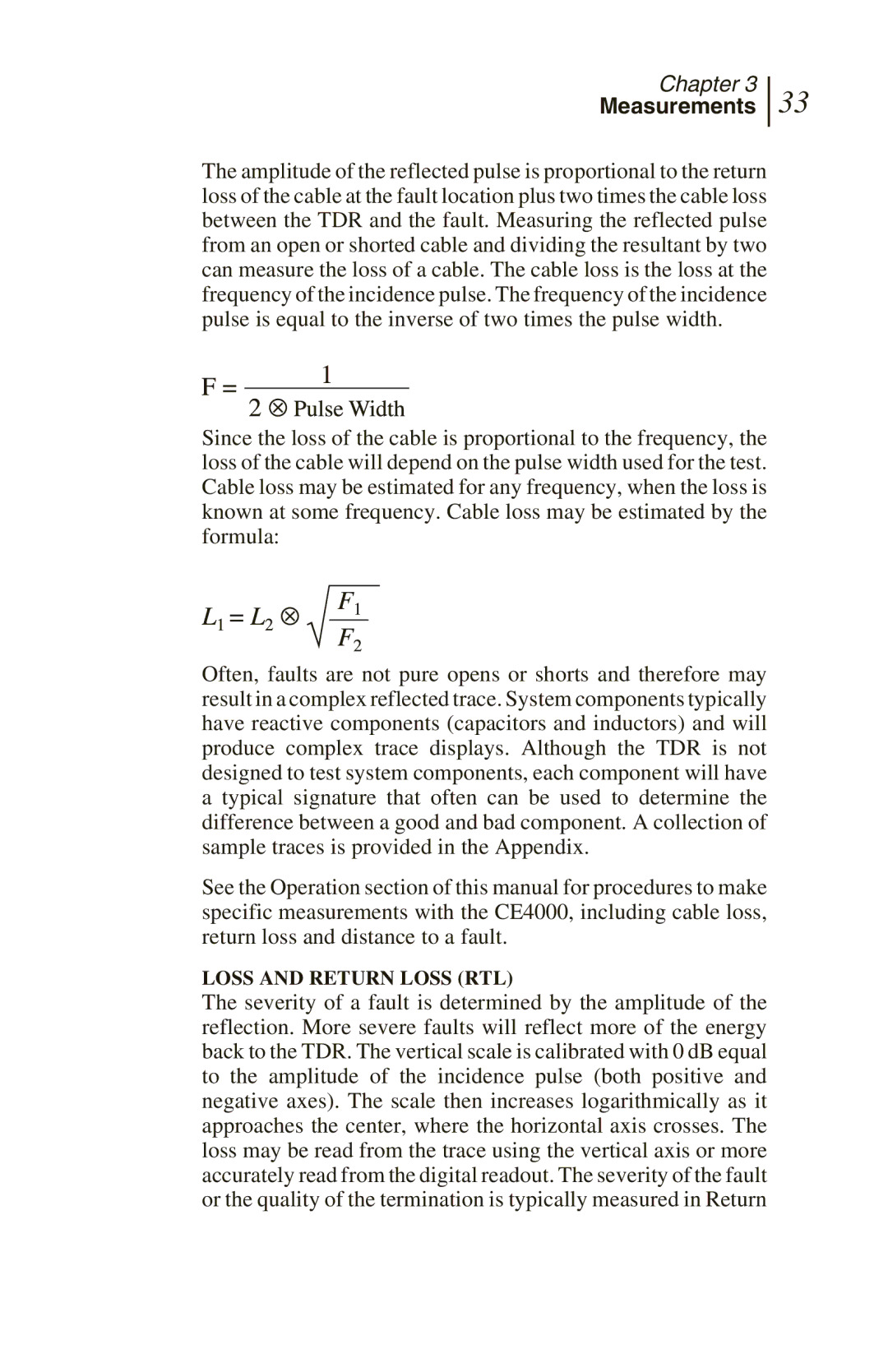
The CE4000 offers pulse widths of 10 nSec, 20 nSec, 50 nSec, 100 nSec, 200 nSec, and 350 nSec. Faults at longer distances may be masked by the cable loss. Longer pulses represent more

Image 30
Contents CE4000 CE4000 Cable Explorer TDR Disclaimer Contents Maintenance And Service Introduction Introduction Instrument OverviewGeneral Information CM1000 Mainframe and CE4000 Module Mainframe Input/OutputCM1000 mainframe and CE4000 module CE4000 Keyboard Functions History Preparation for USE Unpacking And Initial InspectionGeneral Information Shipment Contents Charging InstructionsSafety Precautions First Time Module Installation CE4000 Cable Explorer TDR Setup Power Up To Self Test ScreenGetting Started Main Menu Screen Detail Setup Overview System Setup Detail Time & Date Cable Select Detail Insert Save changes by pressing the Save F3 key Cable Test SET Cable Length Cable Type CE4000 Cable Explorer TDR Locating Cable Faults TDR BasicsMeasurements VOP Measurements TDR Trace Loss and Return Loss RTL Trace Signatures TDR Tests with the CE4000 Auto Test Mode Display CE4000 Cable Explorer TDR Zoom Peak Hold Save Manual TDR Measurements Display M1/M2 Pulse Gain / POS Measurements CE4000 Cable Explorer TDR Stored Files CE4000 Cable Explorer TDR Next Adjust Compare Load Performance Specifications and KEY Features Interfaces PowerEnvironment DisplayMaintenance and Service Battery ReplacementGeneral Maintenance Internal Rechargeable BatteryCleaning Troubleshooting Firmware Upgrades CompactFlash Card ReplacementCE4000 Cable Explorer TDR Warranty Technical SupportReturning Equipment to Sunrise Customer’s ResponsibilityMaintenance and Service CE4000 Cable Explorer TDR Appendix Cable Data Additional Cable dataVOP