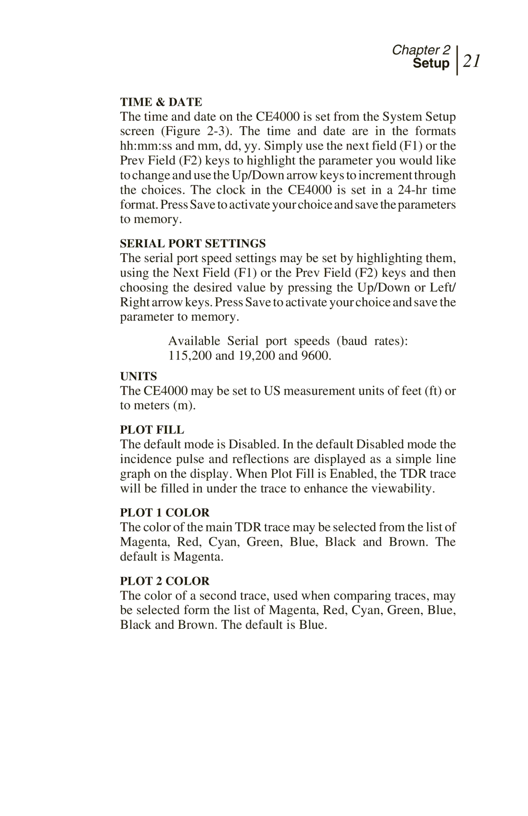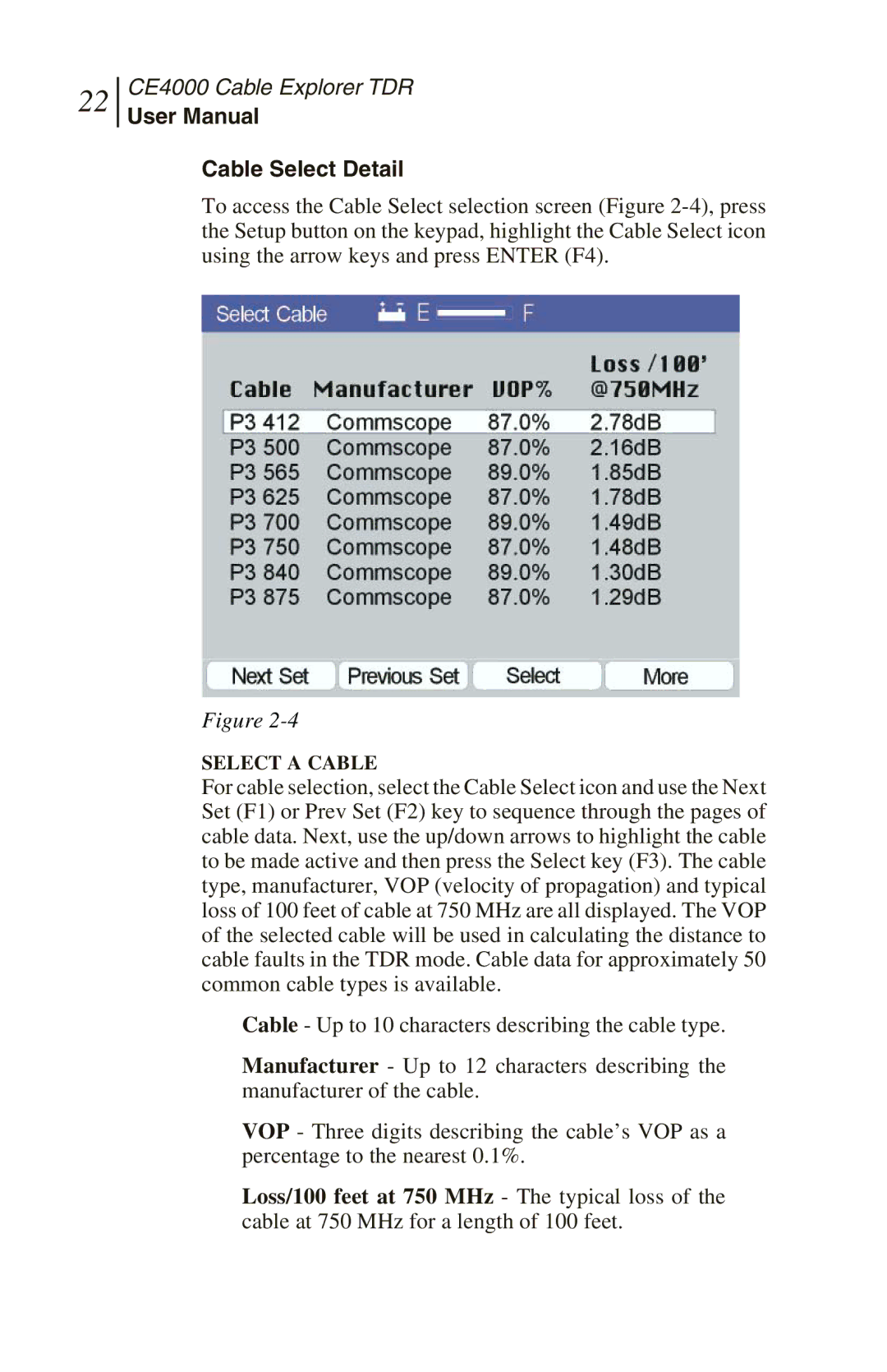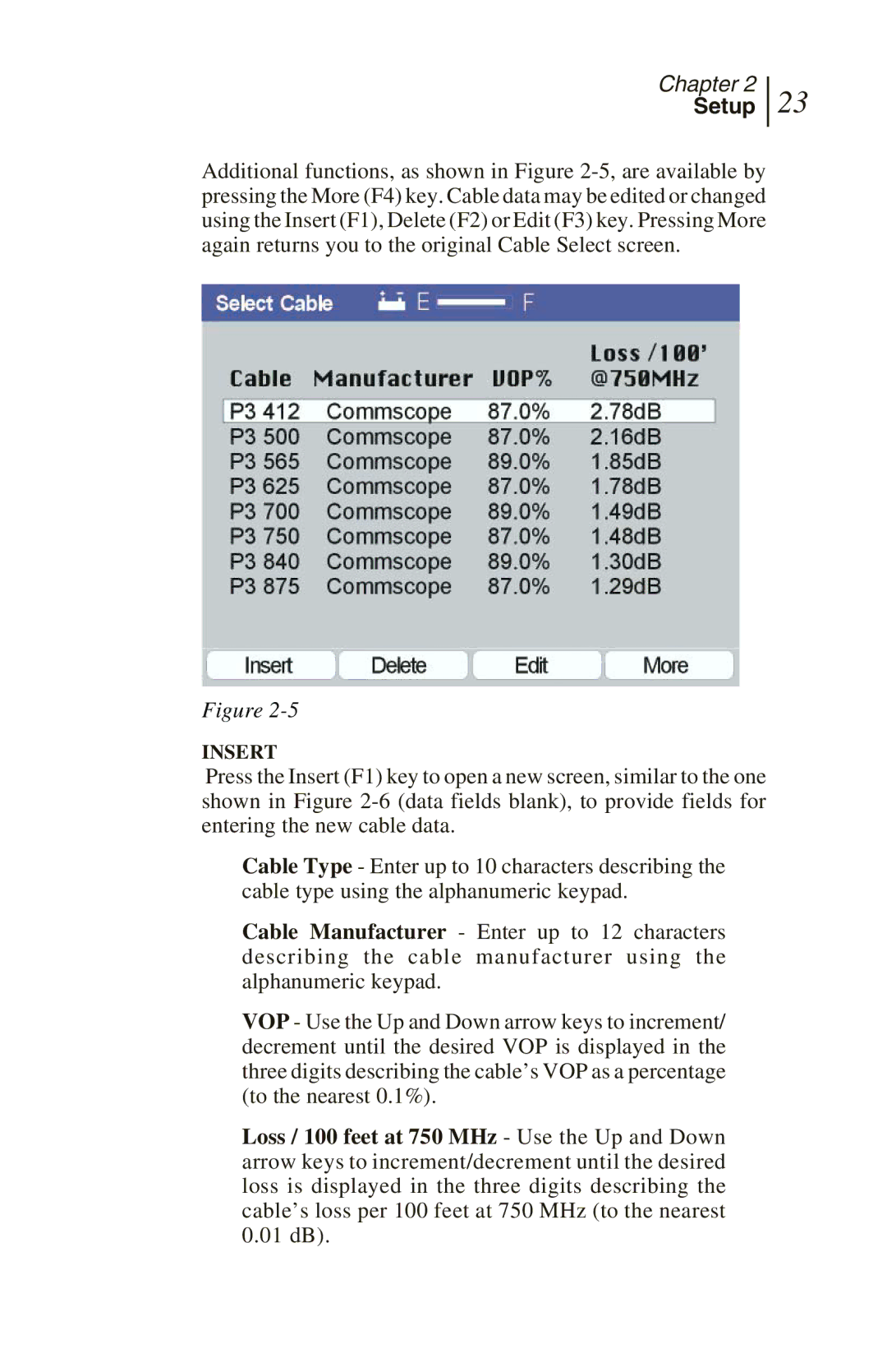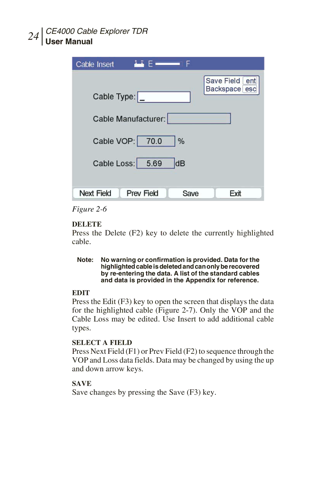
Chapter 3
Measurements
33
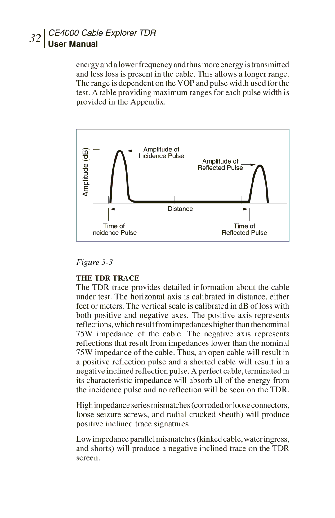
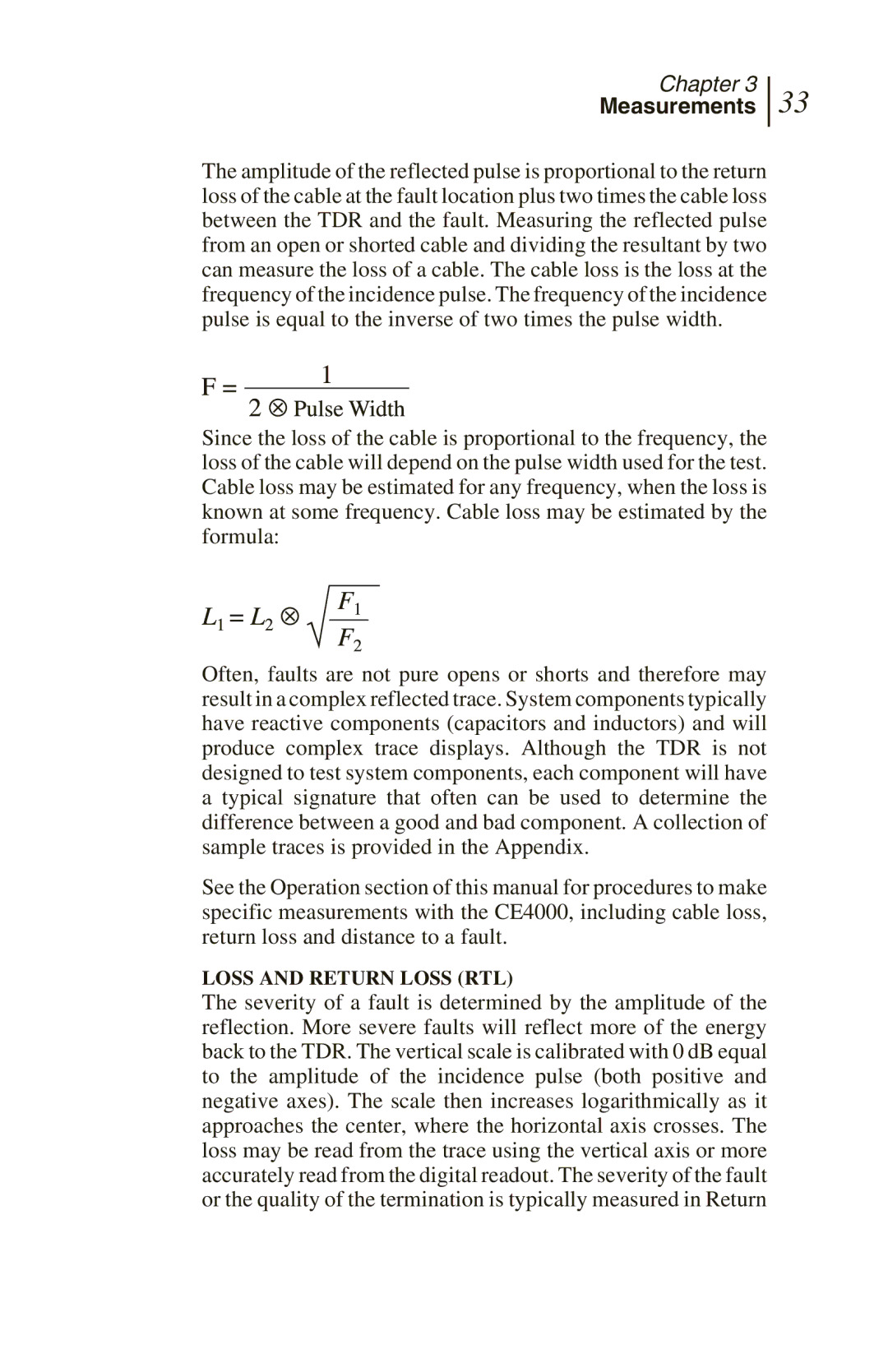
The amplitude of the reflected pulse is proportional to the return loss of the cable at the fault location plus two times the cable loss between the TDR and the fault. Measuring the reflected pulse from an open or shorted cable and dividing the resultant by two can measure the loss of a cable. The cable loss is the loss at the frequency of the incidence pulse. The frequency of the incidence pulse is equal to the inverse of two times the pulse width.
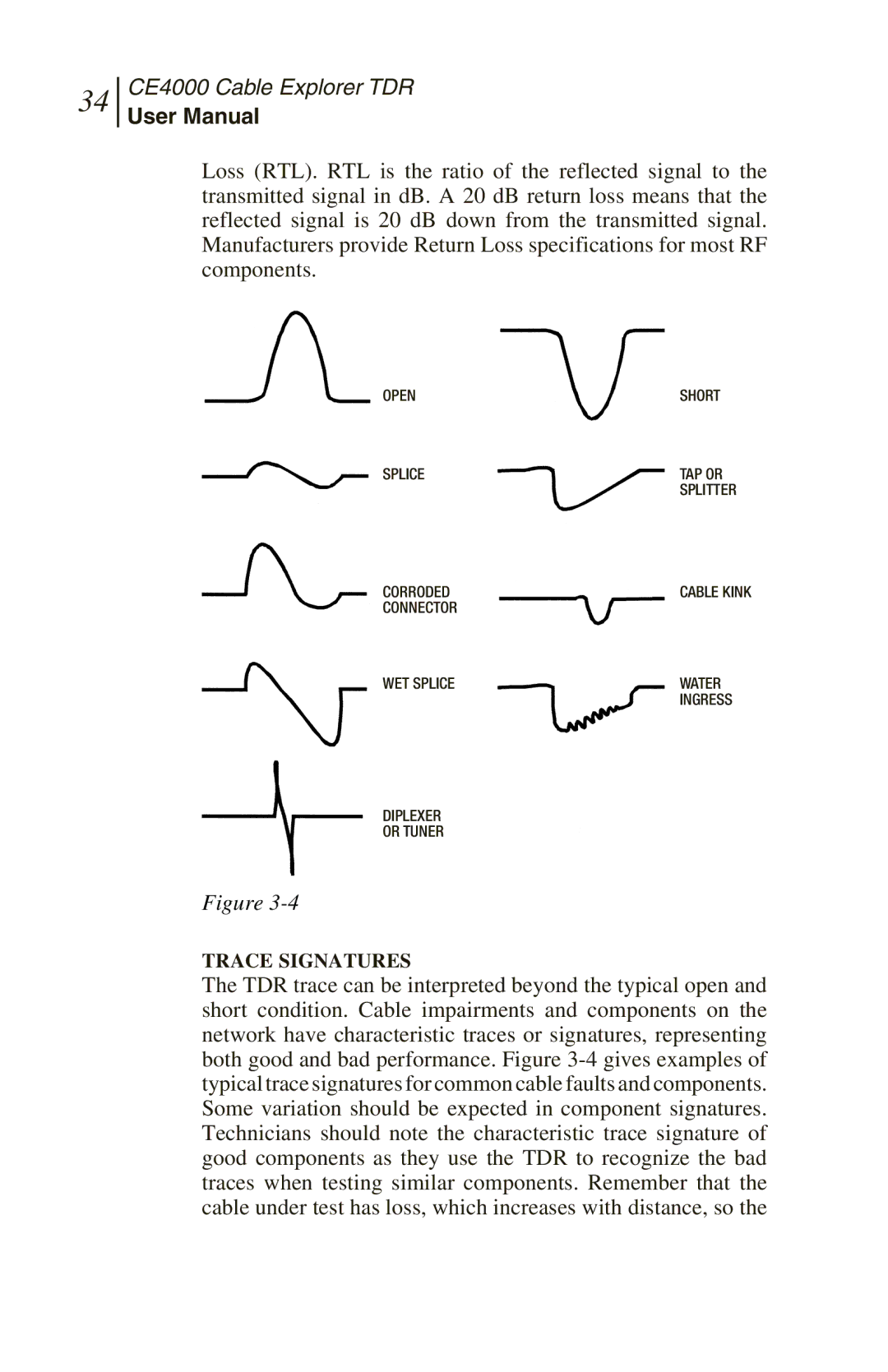
Since the loss of the cable is proportional to the frequency, the loss of the cable will depend on the pulse width used for the test. Cable loss may be estimated for any frequency, when the loss is known at some frequency. Cable loss may be estimated by the formula:
Often, faults are not pure opens or shorts and therefore may result in a complex reflected trace. System components typically have reactive components (capacitors and inductors) and will produce complex trace displays. Although the TDR is not designed to test system components, each component will have a typical signature that often can be used to determine the difference between a good and bad component. A collection of sample traces is provided in the Appendix.
See the Operation section of this manual for procedures to make specific measurements with the CE4000, including cable loss, return loss and distance to a fault.
LOSS AND RETURN LOSS (RTL)
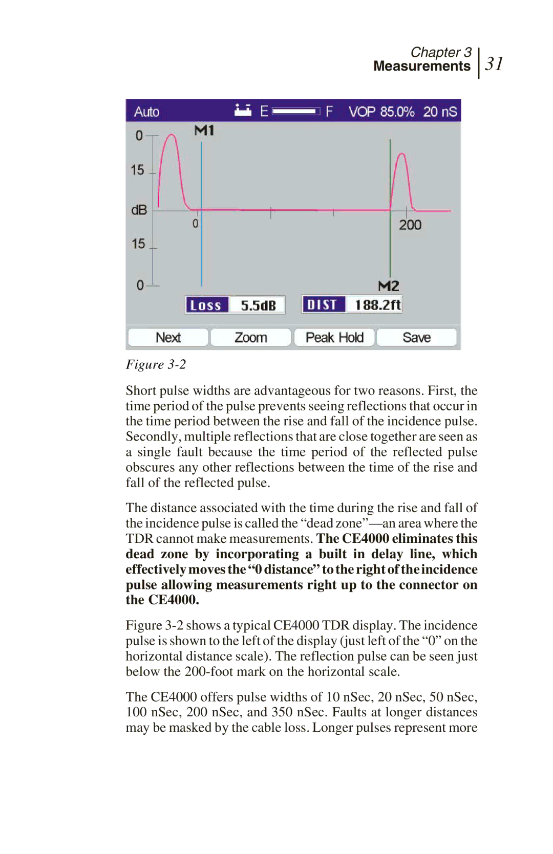
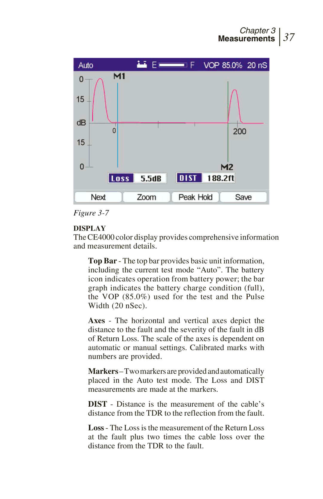
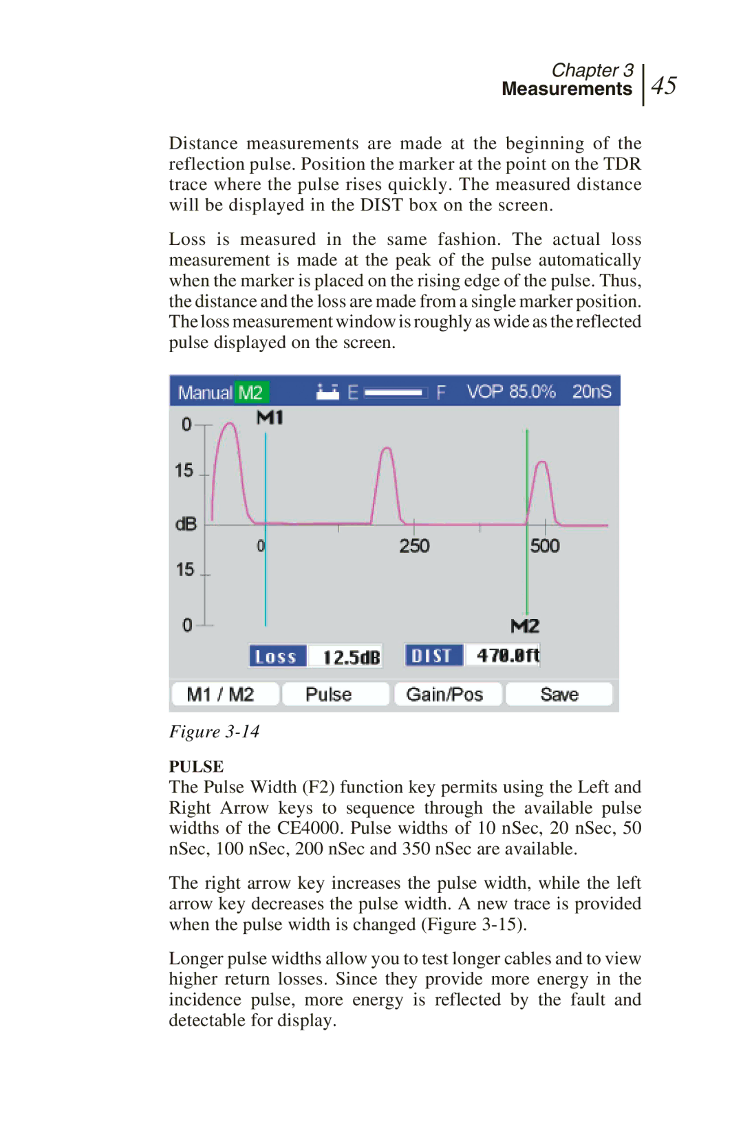
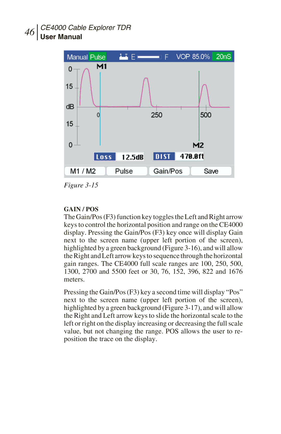
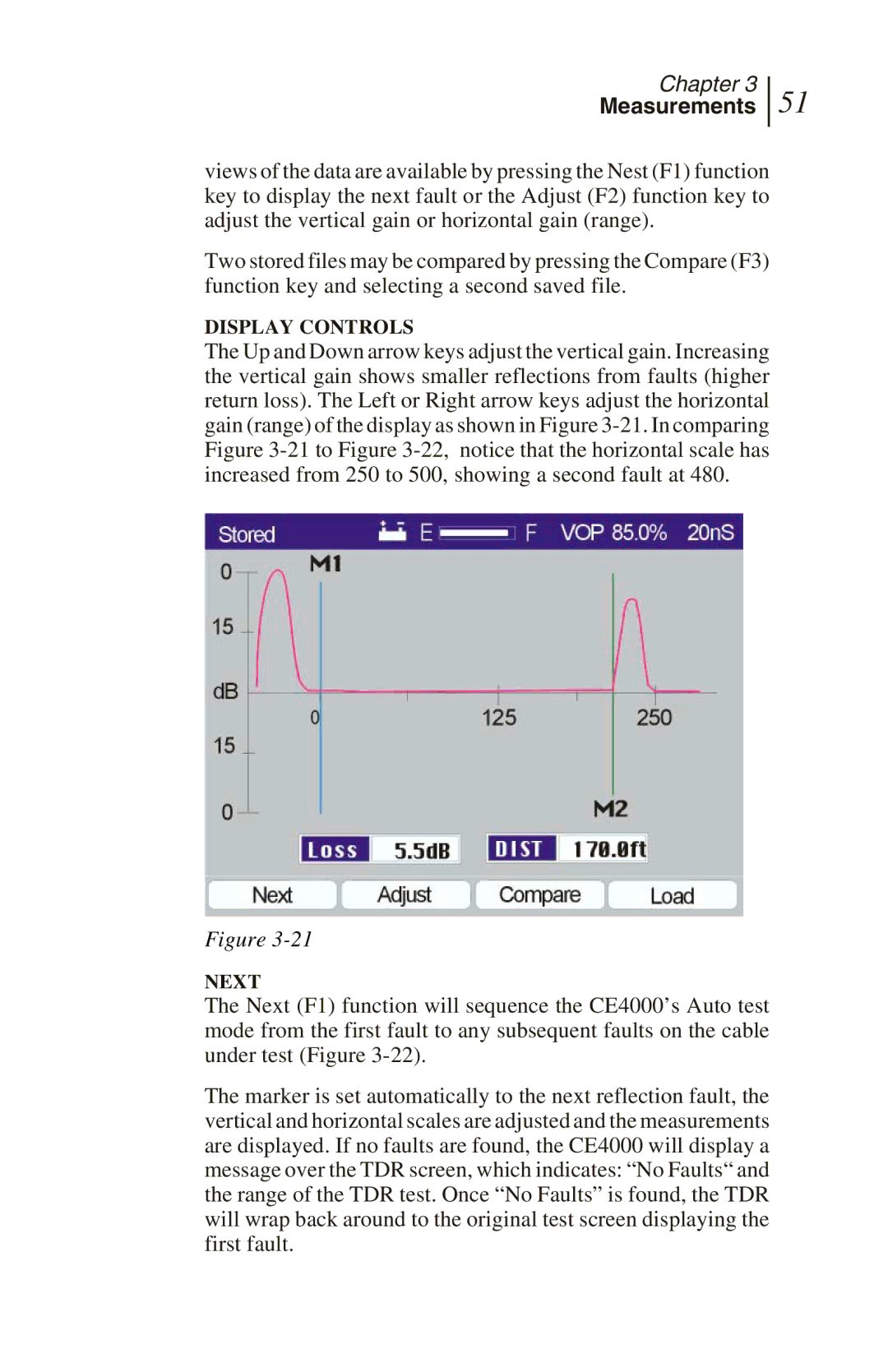
The severity of a fault is determined by the amplitude of the reflection. More severe faults will reflect more of the energy back to the TDR. The vertical scale is calibrated with 0 dB equal to the amplitude of the incidence pulse (both positive and negative axes). The scale then increases logarithmically as it approaches the center, where the horizontal axis crosses. The loss may be read from the trace using the vertical axis or more accurately read from the digital readout. The severity of the fault or the quality of the termination is typically measured in Return
