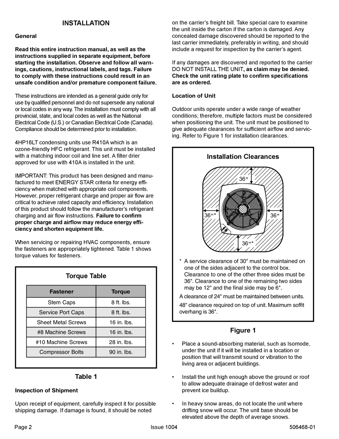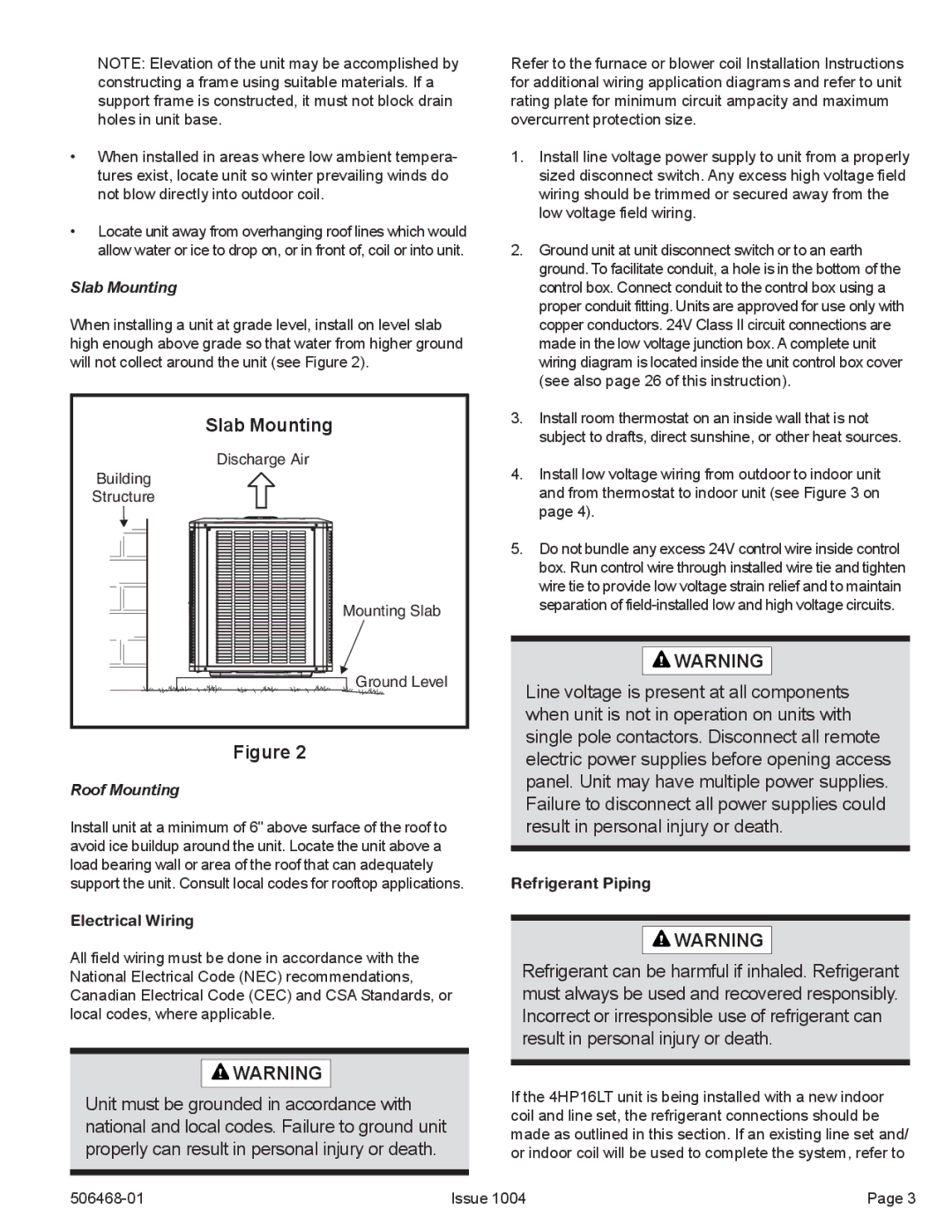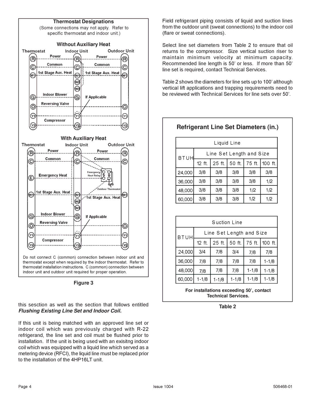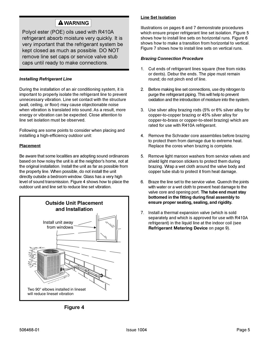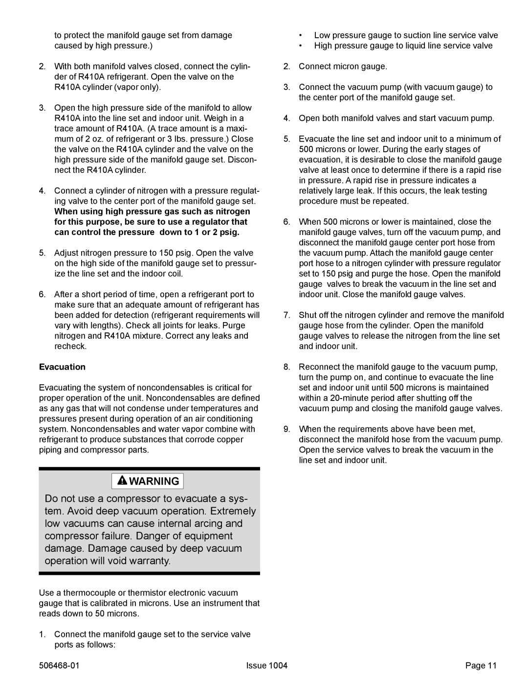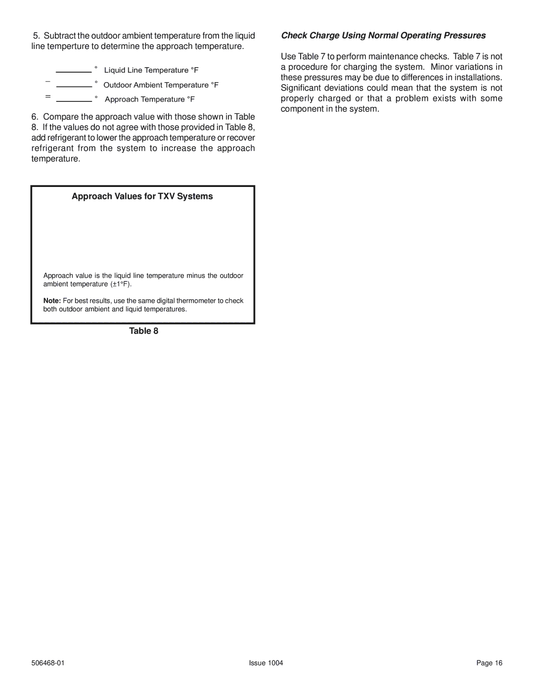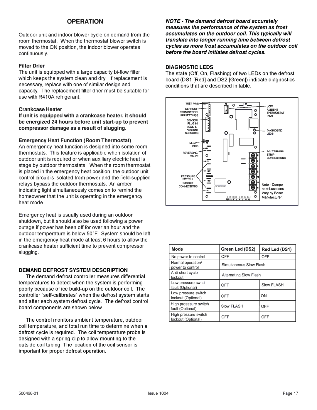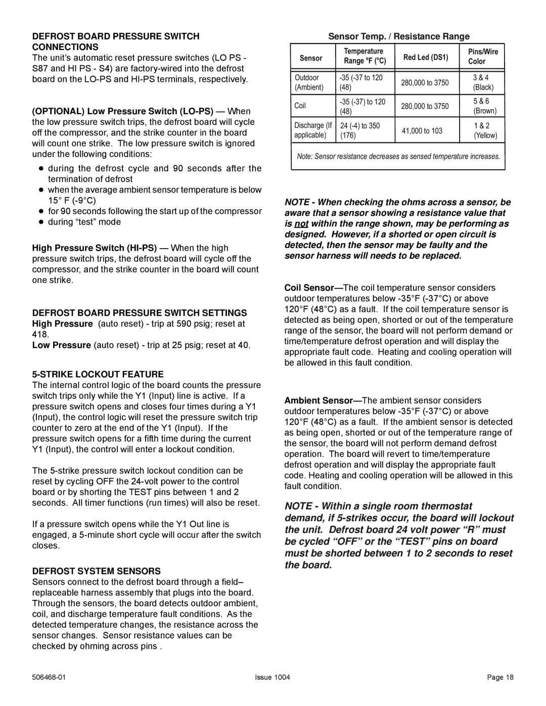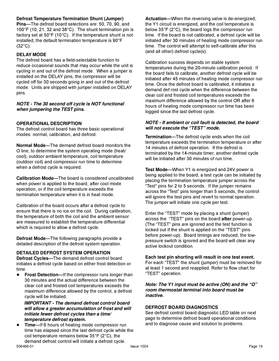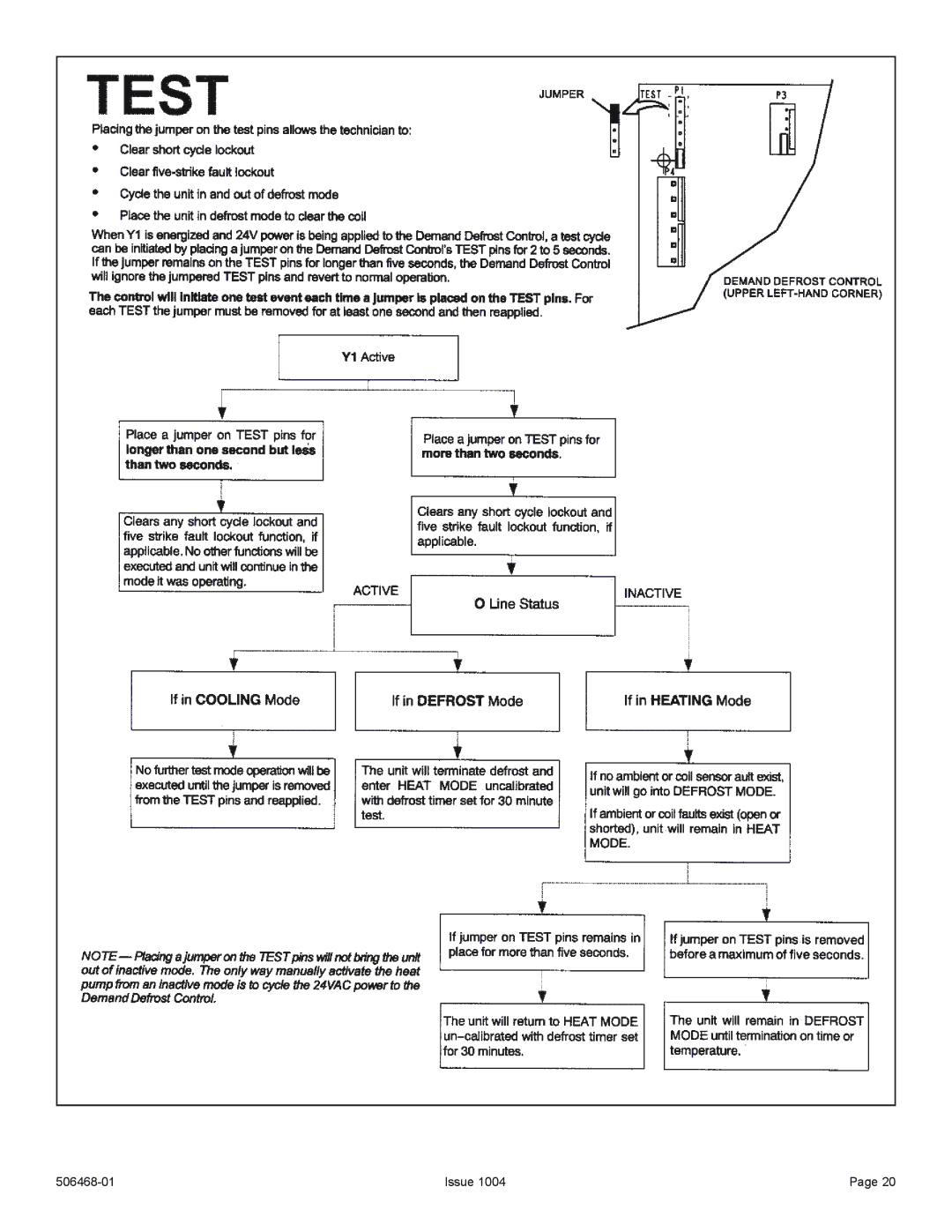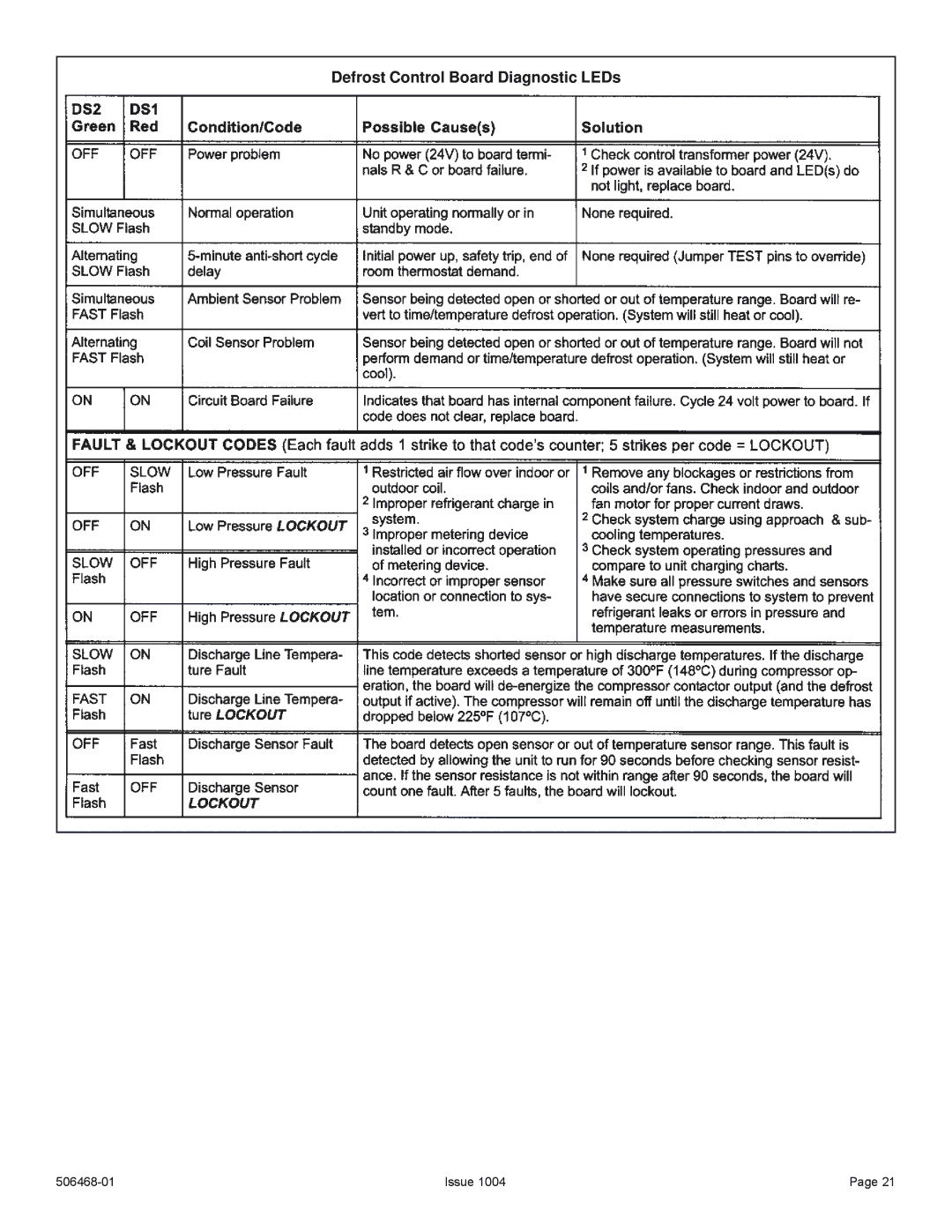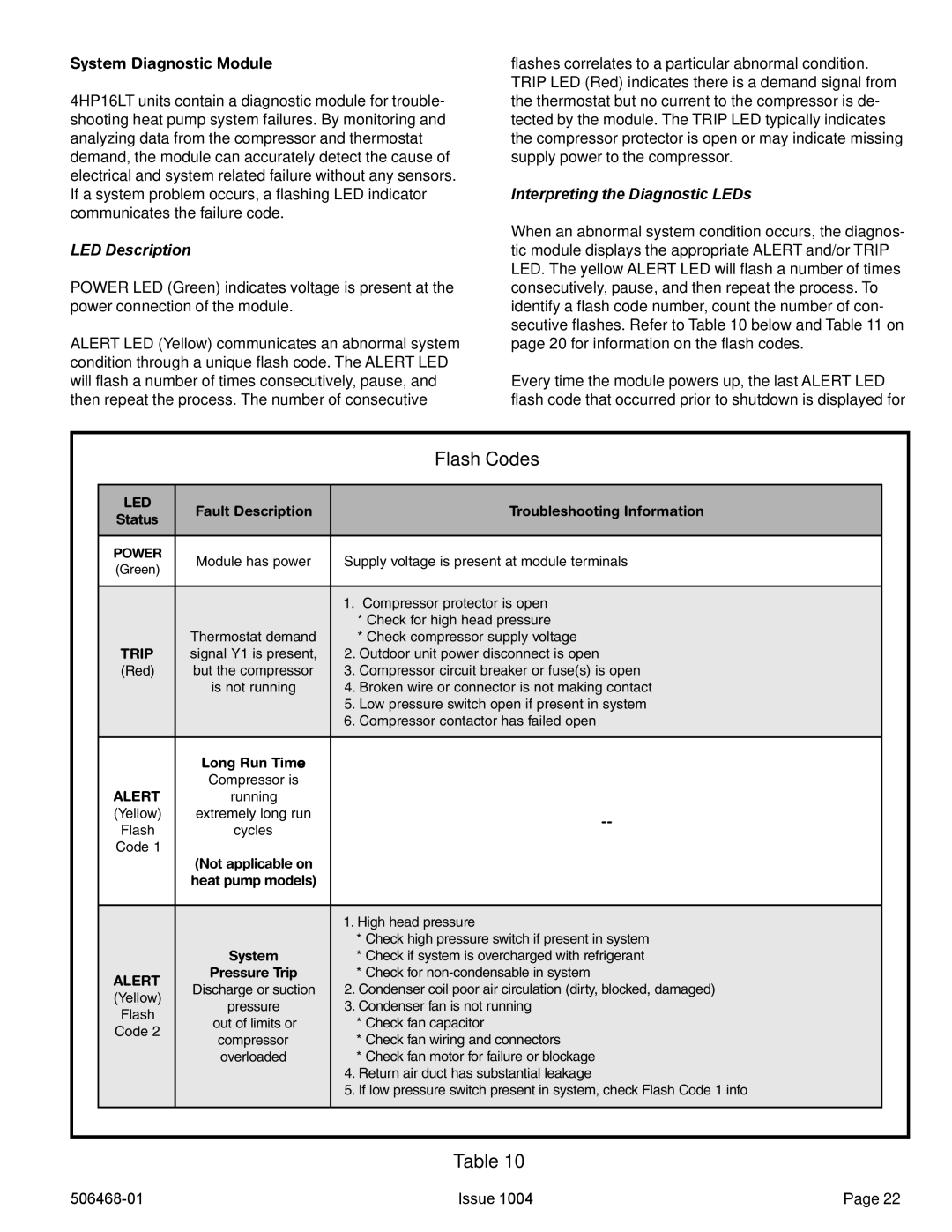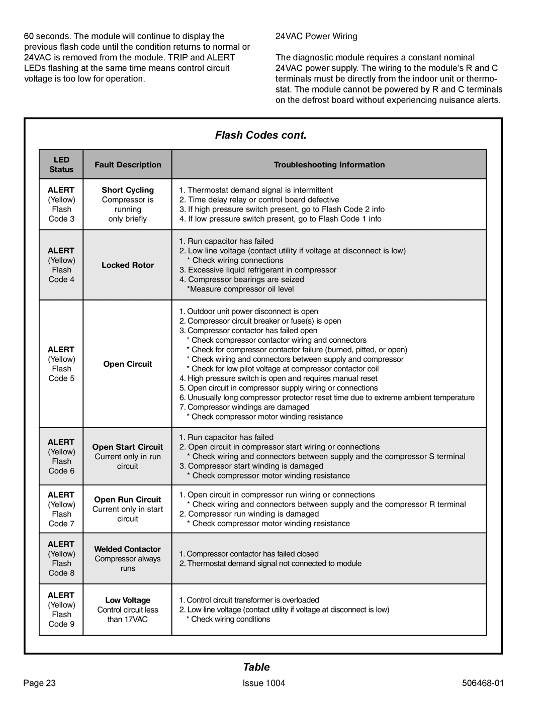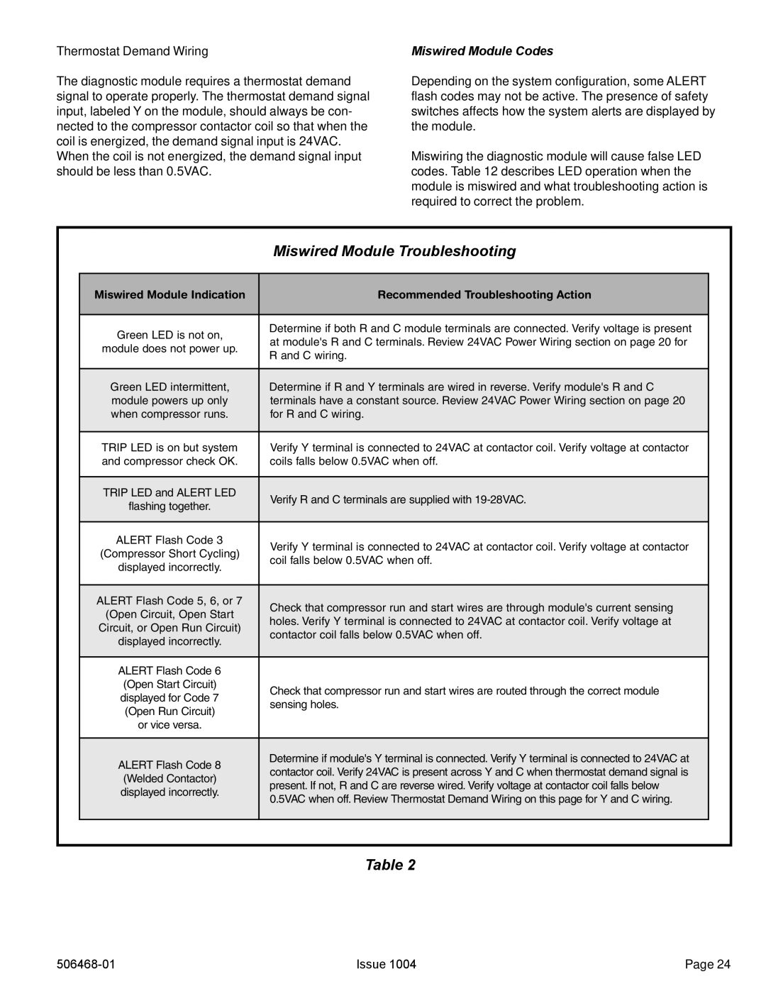
R410A Temperature/Pressure Chart
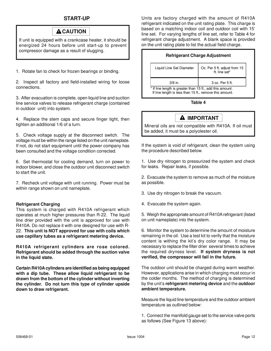
Blocking Outdoor Coil
Temp. | Pressure |
EF | Psig |
|
|
32 | 100.8 |
|
|
33 | 102.9 |
|
|
34 | 105.0 |
|
|
35 | 107.1 |
|
|
36 | 109.2 |
|
|
37 | 111.4 |
|
|
38 | 113.6 |
|
|
39 | 115.8 |
|
|
40 | 118.0 |
|
|
41 | 120.3 |
|
|
42 | 122.6 |
|
|
43 | 125.0 |
|
|
44 | 127.3 |
|
|
45 | 129.7 |
|
|
46 | 132.2 |
|
|
47 | 134.6 |
|
|
48 | 137.1 |
|
|
49 | 139.6 |
|
|
50 | 142.2 |
|
|
51 | 144.8 |
|
|
52 | 147.4 |
|
|
53 | 150.1 |
|
|
54 | 152.8 |
|
|
55 | 155.5 |
|
|
56 | 158.2 |
|
|
57 | 161.0 |
|
|
58 | 163.9 |
|
|
59 | 166.7 |
|
|
60 | 169.6 |
|
|
61 | 172.6 |
|
|
62 | 175.5 |
|
|
63 | 178.5 |
|
|
64 | 181.6 |
|
|
65 | 184.3 |
|
|
66 | 187.7 |
|
|
67 | 190.9 |
|
|
68 | 194.1 |
|
|
69 | 197.3 |
|
|
70 | 200.6 |
|
|
71 | 203.9 |
|
|
72 | 207.2 |
|
|
73 | 210.6 |
|
|
Temp. | Pressure |
EF | Psig |
|
|
74 | 214.0 |
|
|
75 | 217.4 |
|
|
76 | 220.9 |
|
|
77 | 224.4 |
|
|
78 | 228.0 |
|
|
79 | 231.6 |
|
|
80 | 235.3 |
|
|
81 | 239.0 |
|
|
82 | 242.7 |
|
|
83 | 246.5 |
|
|
84 | 250.3 |
|
|
85 | 254.1 |
|
|
86 | 258.0 |
|
|
87 | 262.0 |
|
|
88 | 266.0 |
|
|
89 | 270.0 |
|
|
90 | 274.1 |
|
|
91 | 278.2 |
|
|
92 | 282.3 |
|
|
93 | 286.5 |
|
|
94 | 290.3 |
|
|
95 | 295.1 |
|
|
96 | 299.4 |
|
|
97 | 303.8 |
|
|
98 | 308.2 |
|
|
99 | 312.7 |
|
|
100 | 317.2 |
|
|
101 | 321.8 |
|
|
102 | 326.4 |
|
|
103 | 331.0 |
|
|
104 | 335.7 |
|
|
105 | 340.5 |
|
|
106 | 345.3 |
|
|
107 | 350.1 |
|
|
108 | 355.0 |
|
|
109 | 360.0 |
|
|
110 | 365.0 |
|
|
111 | 370.0 |
|
|
112 | 375.1 |
|
|
113 | 380.2 |
|
|
114 | 385.4 |
|
|
115 | 390.7 |
|
|
Temp. | Pressure |
EF | Psig |
116396.0
117401.3
118406.7
119412.2
120417.7
121423.2
122428.8
123434.5
124440.2
125445.9
126451.8
127457.6
128463.5
129469.5
130475.6
131481.6
132487.8
133494.0
134500.2
135506.5
136512.9
137519.3
138525.8
139532.4
140539.0
141545.6
142552.3
143559.1
144565.9
145572.8
146579.8
147586.8
148593.8
149601.0
150608.1
151615.4
152622.7
153630.1
154637.5
155645.0
Outdoor coil should be blocked one side at a time with cardboard or plastic sheet until proper testing pressures are reached.
![]() CARDBOARD OR
CARDBOARD OR
PLASTIC SHEET
Figure 13
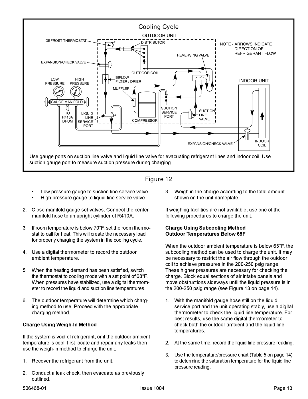
4.Subtract the liquid line temperature from the saturation temperature (according to the chart) to determine Subcooling.
°Saturation Temperature °F
_
° Liquid Line Temperature °F
=° Subcooling Value °F
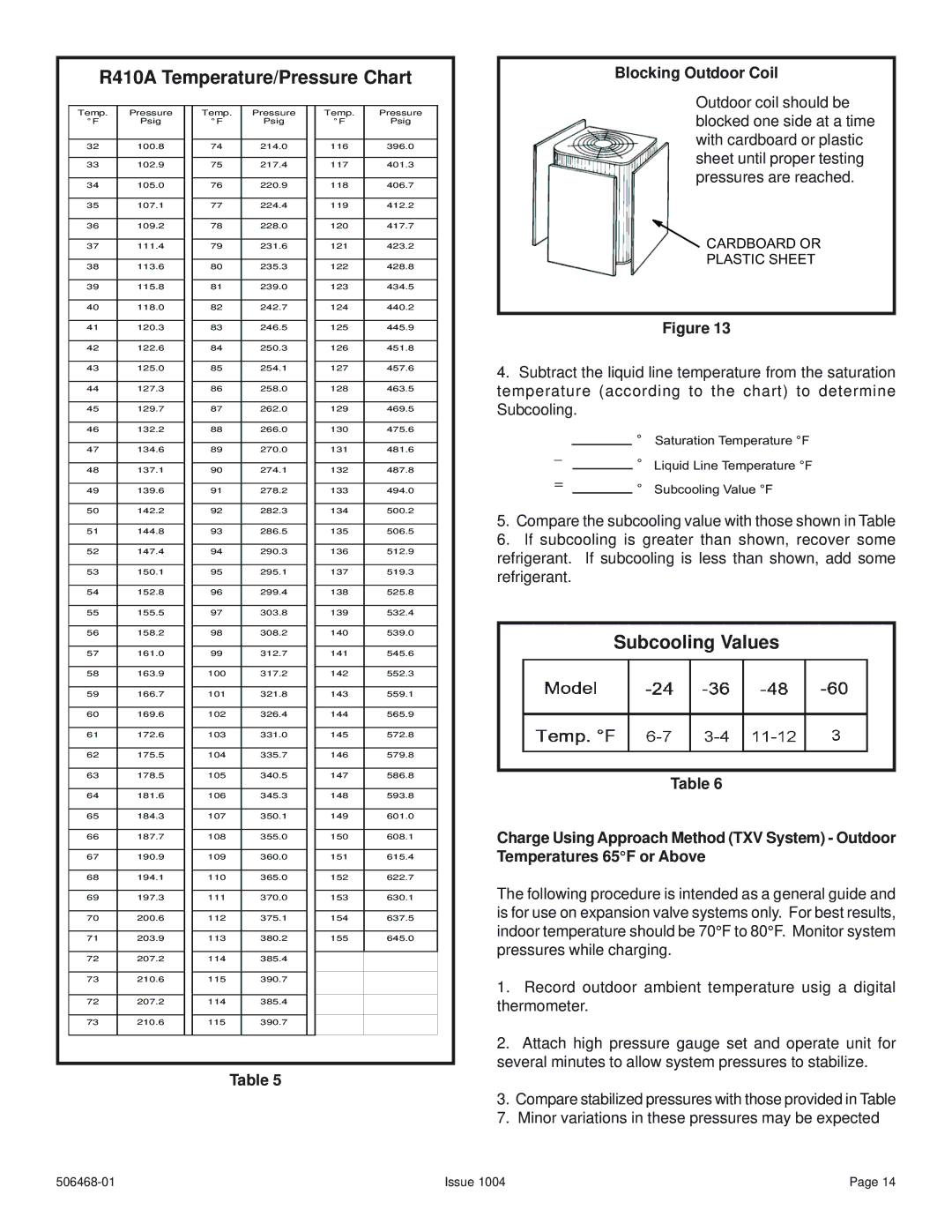
5.Compare the subcooling value with those shown in Table
6.If subcooling is greater than shown, recover some refrigerant. If subcooling is less than shown, add some refrigerant.
Subcooling Values
Table 6
Charge Using Approach Method (TXV System) - Outdoor Temperatures 65°F or Above
The following procedure is intended as a general guide and is for use on expansion valve systems only. For best results, indoor temperature should be 70°F to 80°F. Monitor system pressures while charging.
1. Record outdoor ambient temperature usig a digital |
72 | 207.2 |
| 114 | 385.4 |
|
|
|
|
|
|
|
|
|
|
|
73 | 210.6 |
| 115 | 390.7 |
|
|
|
|
|
|
|
|
|
|
|
Table 5
thermometer. | |
2. | Attach high pressure gauge set and operate unit for |
several minutes to allow system pressures to stabilize. | |
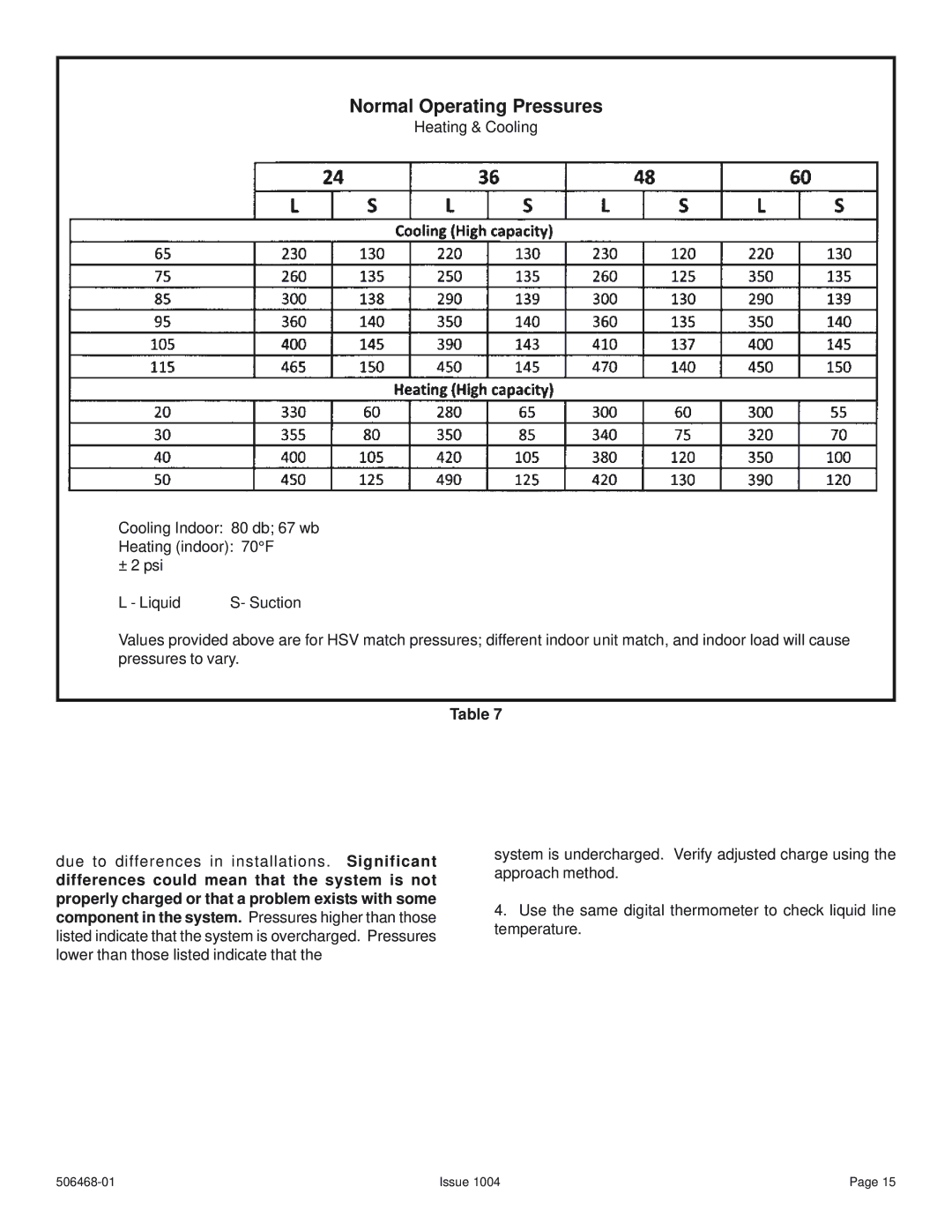
3. | Compare stabilized pressures with those provided in Table |
7. | Minor variations in these pressures may be expected |
Issue 1004 | Page 14 |
