Craftsman 315.220381 Installing Control CUT Device, Barrel Carriage Assembly SOCKETF.34

Page 42

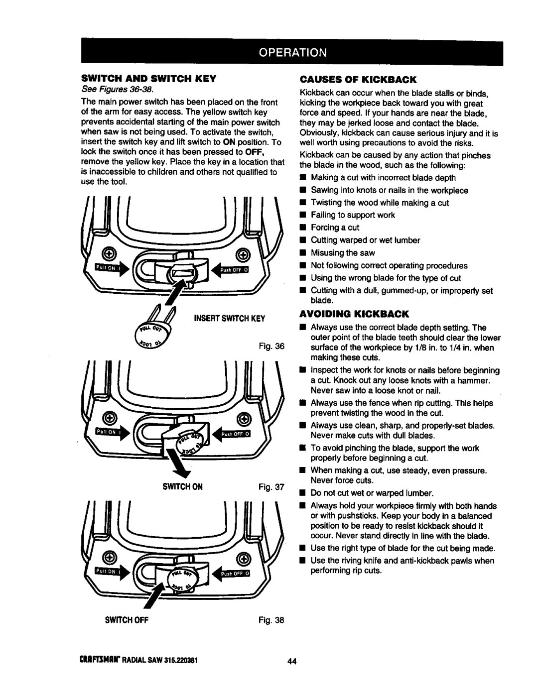
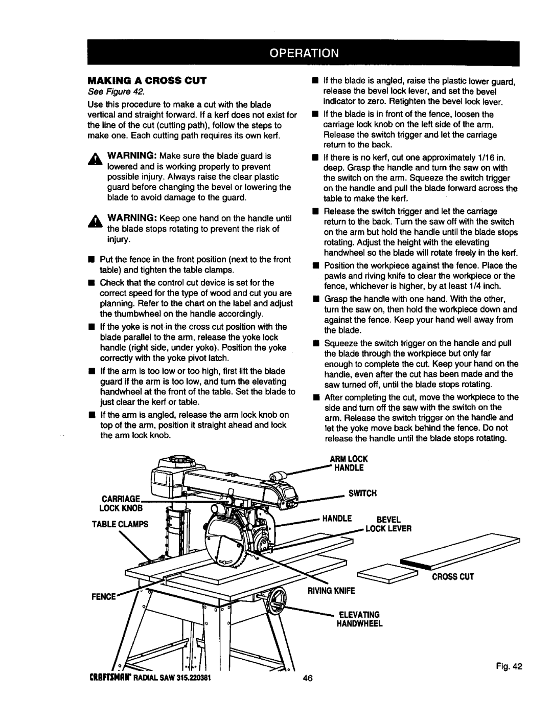
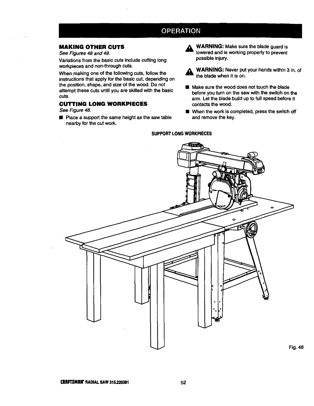
INSTALLING CONTROL CUT DEVICE

See Figure 34.

Note: Before installing the controlcut device, the yoke assembly will travel back and forward on the carriage by pullingthe handle. After installing the controlcut device, the power cordfor the controlcut device must be plugged in and

switch triggerpressed to move the yoke assembly and carriage on the arm.

WARNING: Do not install the control cut device until after all of the initial adjustments and alignments are made to prevent accidental starting of the saw that could result in serious personal injury.

The control cut device offers many benefits.As it Increases operator control,It eliminatesthe risk in a cross cut of the saw "climbing"out and over the

workplace at the operator. Feed control of the blade as it cuts throughthe workpiece increases,as does the accuracy of the cut.

The control cutcable maintainsa steady pullon the carriage assemblyfrom the column.This tension keeps the assembly at the column,unlessyou

squeeze the switchtrigger in the hendte.The switch triggeractivatesthe motor to counter the pullof the cable.

After a cut is completed, press the switchon the arm off, then release the switch triggerto preventfurther forward motion.Hold the handle until the blade has stopped rotating.The yoke assembly will not roll forward unlessyou are squeezing the switch trigger.

The control cut power cord is designedto operate on

asingle voltageAC circuit.The speed can be set with a thumbwheelon top of the handle. The three speed settingsare describedon the label locatedon the left side of the control cut housing.

_k WARNING: Do not use the saw withoutthe controlcut and blade guards in place unless

specifically Instructed to do so. Otherwise uncontrolled contact with the blade could occur, resulting in personal injury.

_1= WARNING: Take great care when working with either cord to ensure you have the correct one. If

you Intend to unplug the main power cord but remove the control cut cord Instead, the blade could be accidentally started and cause

Injury.

Plug in the controlcut cord, leavingthe main power cord disconnected.Squeeze the switchtriggerto confirm the control cut motoris receivingpower.

On the left side of the saw, remove the carriage lock knob and spdng. Remove the two screws that attach the carriage cover and remove the cover.

Replace the spring and cardage lock knob. Pull the carriage assembly about halfway to the front. Tighten the carriage lock knob.

Squeeze the switch trigger in the handle with your right hand and pull the spring loaded cable from the column with your left hand. If you prefer to use a pair of pliers, do not damage the cable. Note: Do not to let the spring loaded cable clamp slip out of your hand or pliers. If it slips past the cable bracket and goes up Into the control cut motor housthg, then disassembly of the control cut assembly will be required to get it back out.

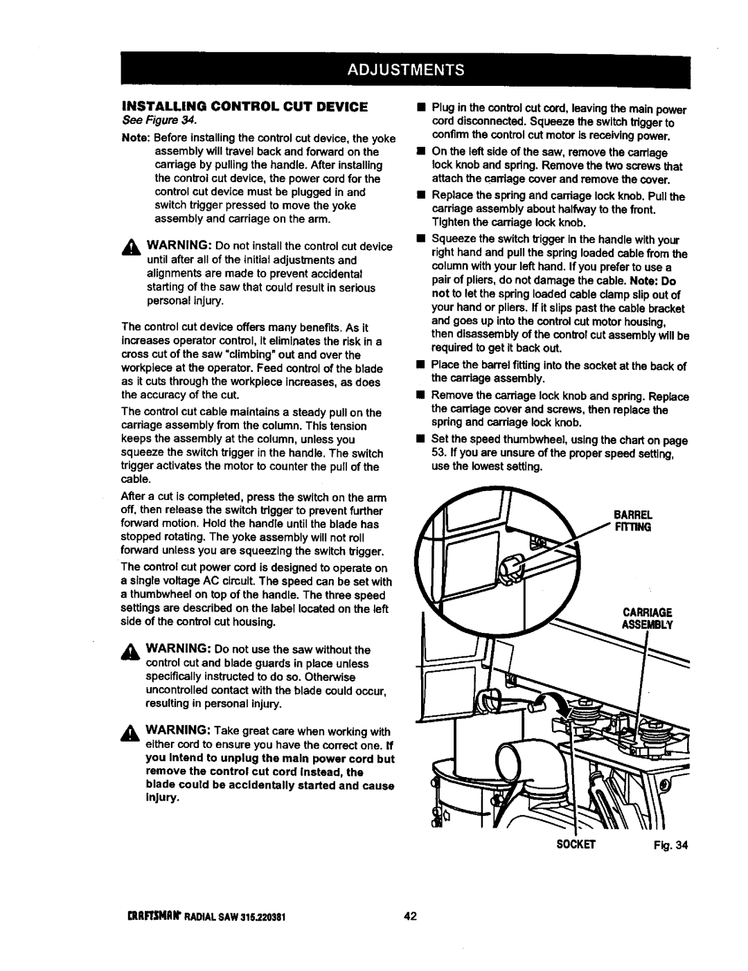
Place the barrel fitting into the socket at the back of the carriage assembly.

Remove the carriage lock knob and spring. Replace the carriage cover and screws, then replace the spring and carriage lock knob.

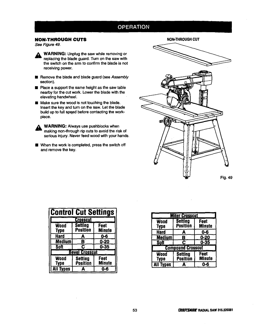
Set the speed thumbwhee], using the chart on page

53.If you are unsure of the proper speed setting, use the lowest setting.

BARREL

CARRIAGE

ASSEMBLY

SOCKETF_.34

[ItlIFTSNAItRADIAL SAW 315.?.20381

42

Image 42
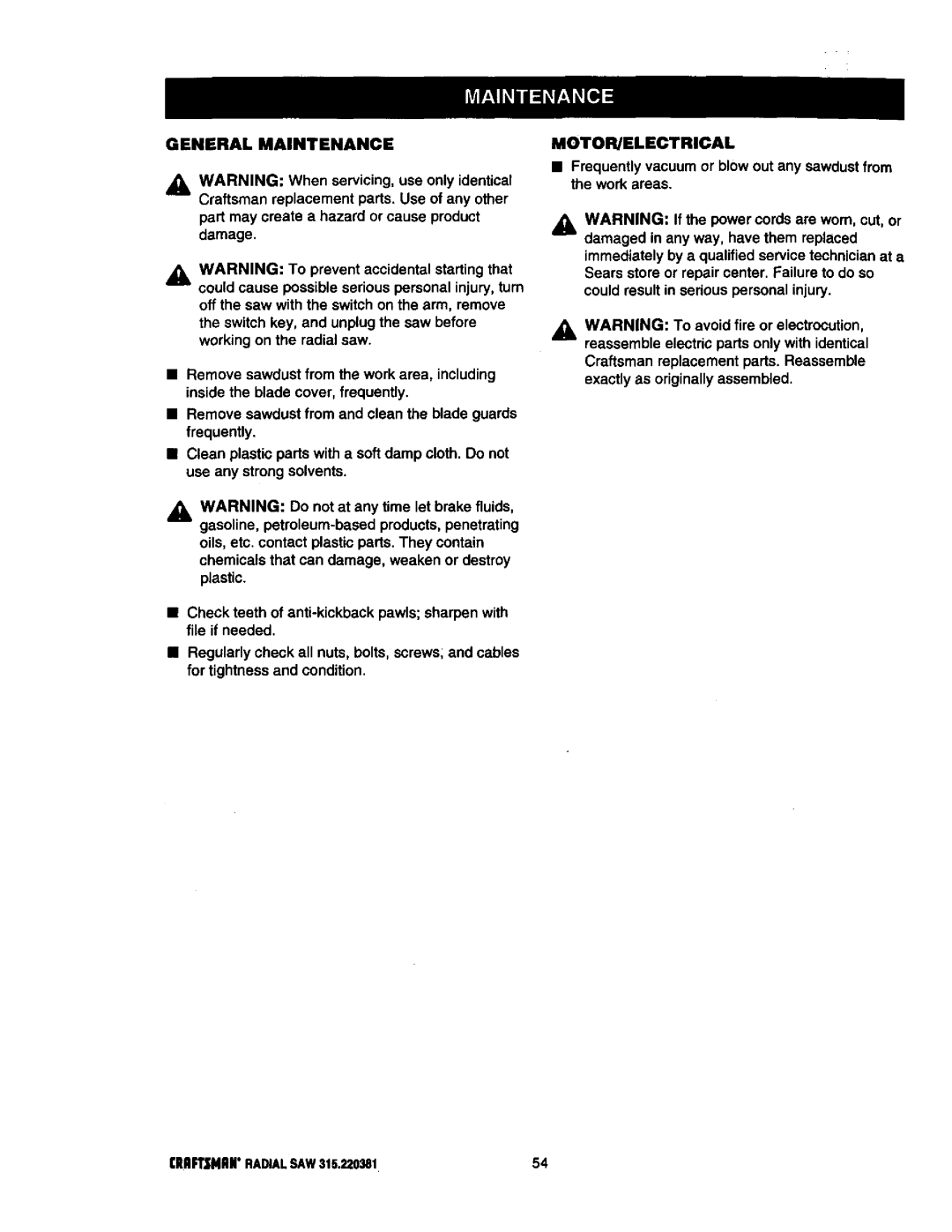
Contents Radial ARM SAW Ofess IonalFull ONE Year Warranty on Craftsman Radial ARM SAW 28-29 Symbol Meaning Safety Alert SymbolAvoid Awkward Operations and Hand Be Sure the Blade Clears the Work RIP only Workpieces Longer than Groundinginstructions Grounding PIN Coverofgrounded OutletboxChanging Voltage See FiguresBladearbor BladeBevelAngle GumRAFTSNANRADIALSAW315,220381 Sawassemblyshownaspacked IIoII Cdef000 Io@C LevelInch Radii Arm Saw RE.ANTPARTSAdvertencia Knowyourradialsaw See aYoke Miterscale Armlockknob Yokepivotlatch RIP FeatureslistSee Figures 9A-9D 19IIRFTSMRNRADIALSAW315.220381Figures 9A and 9B MOTOR13/6.5AMP- Powersthebladeand is Dustguide HolddownSee Figure I OA Assembly and Adjustments sections beforeTighten. See Figure I OA See Figure lOBSAW Base LEG Sawbase Hexbolt Flat Washer Lockwasher Mounting SAW to LEG Stand Attaching Elevating HandwheelSee Figure Elevating Shaft Handwheel Screw StarwasherArmlockknob ARM Capscrews Installing the Yoke AssemblyArmviewedfrombelow Carriagearm LockknobBlade Arbor Mounttablesupports Usingtheseholelocations Removing the BladeAttaching Table Supports See Figures 17,4and 17B Setting the ARM Lock KnobArmcap Motor Yokelock Handle Assembly Yokelock HandleBevellockleverin Setting the Bevel Lock LeverStarwasher Bevel Bevel BevelSee Figures 20A 20D Rear Coverscrews HEXBOLT2 HEXNUT2 Adjusting the Column TubeTightening the ARM and Column Column ARM Tube SupportColumntube Elevation AdjustmentRotation Adjustment Silverblack Screws ColumnsupportAdjusting the Carriage Bearings CarriagebearingEccentricscrew Wrench Graspandhold Carriagebearing Blade Wrenchat Front Armlockknob Leveling Table SupportsSee Figures 22A and 22B Rightside Tablesupport23A Installing the Front TableSee Figures 23A 23C HexnutLeveling the Front Table See Figures 25A 25CReartablefence Spacertablefronttable Clamp Bracket Squarenut HoleBlade Rotation Hten WRENCH2 See Figures 27A 27C Installing RIP Scale Indicators Carriage SpeednutSpring Carriage Screws Lockknob Aligning the ARM for Cross Cuts See Figures 29,4 2gCIndexcap Bevel Aligning Blade to Table AT 0 BevelSee Figures 30A 30D Lock Lever Fronttable Socket Elevating Headscrews HandwheelHexbolts Squaring Blade to FenceSee Figures 31A 31C Framingsquare YokelockhandleParalleling Blade to Table Noadjustment Needed BevelAdjustment GAP See Figures 32A-32CAligning the RIP Scale Indicators IN-RIPSCALEONRIGHTSIDEOFARM RIP-SCALEINDICATORSee Figures 33A 33B Installing Control CUT Device Barrel Carriage Assembly SOCKETF.34Cross Cuts Basic Operation of the Radial ARM SAWTypes of Cuts RIP CutsSwitch and Switch KEY Insertswitchkey Switchon Switchoff Causes of KickbackAvoiding Kickback Featnerboards PushsticksPushblocks Pushsticks Pushblocks FeatherboardMaking a Cross CUT Carnage Lockknob TableclampsMaking a Miter CUT Making a Bevel CUT Making a Compound Cross CUT Beveledand Elevating HandwheelYoke Armpivotlatch Swwchyokelock Handle RIP CUT Hazards and Precautions Setting UP a RIP CUTElevating Handwheel Infeedfor Ripcutting See Figure Review the Hazards and Precautions Making a RIP CUTCutting Long Workpieces Making Other CutsSee Figures 48 SupportlongworkpiecesNON-THROUGH CutsGeneral Maintenance MOTOR/ELECTRICALProblem Cause SolutionProblem Remove handwheel clean and lubricate the shaft Adjustmentssection See Adjusting the ColumnTube in Assembly section See Squaring the Blade toCause Solution Fence in AdjustmentssectionAssembly section Seefigure Description Quan Craftsmanradial ARM SAW- ModelnoKEY Part Number KEY PartFigureb Craftsman Radial ARM SAW Model no KEY Part NO.NUMBER63CRRFTSMRNRADIALSAW315.220381 Figurec Parts List for Figure C Descripon QuanFigured Parts List for Figure D 67CRRFTSNHNRADIALSAW315220381Figuree Parts List for Figure E Figuref See Figure G976287-001 71CRAFTSMANRADIALSAW315.220381See Figure F Seefigureh CRAFTSMANTABLESAW315,22038172Parts List for Figure G 73CRRPTSNRNRADIALSAW315.220381Figureh Parts List for Figure H Descripon OuanFigurei Parts List Craftsmanradial ARM SAW ModelnoFigurej Parts List for Figure J Craftsmanradial ARM SAW- Modelno ,220381Figurek Parts List for Figure K Parts Direct s