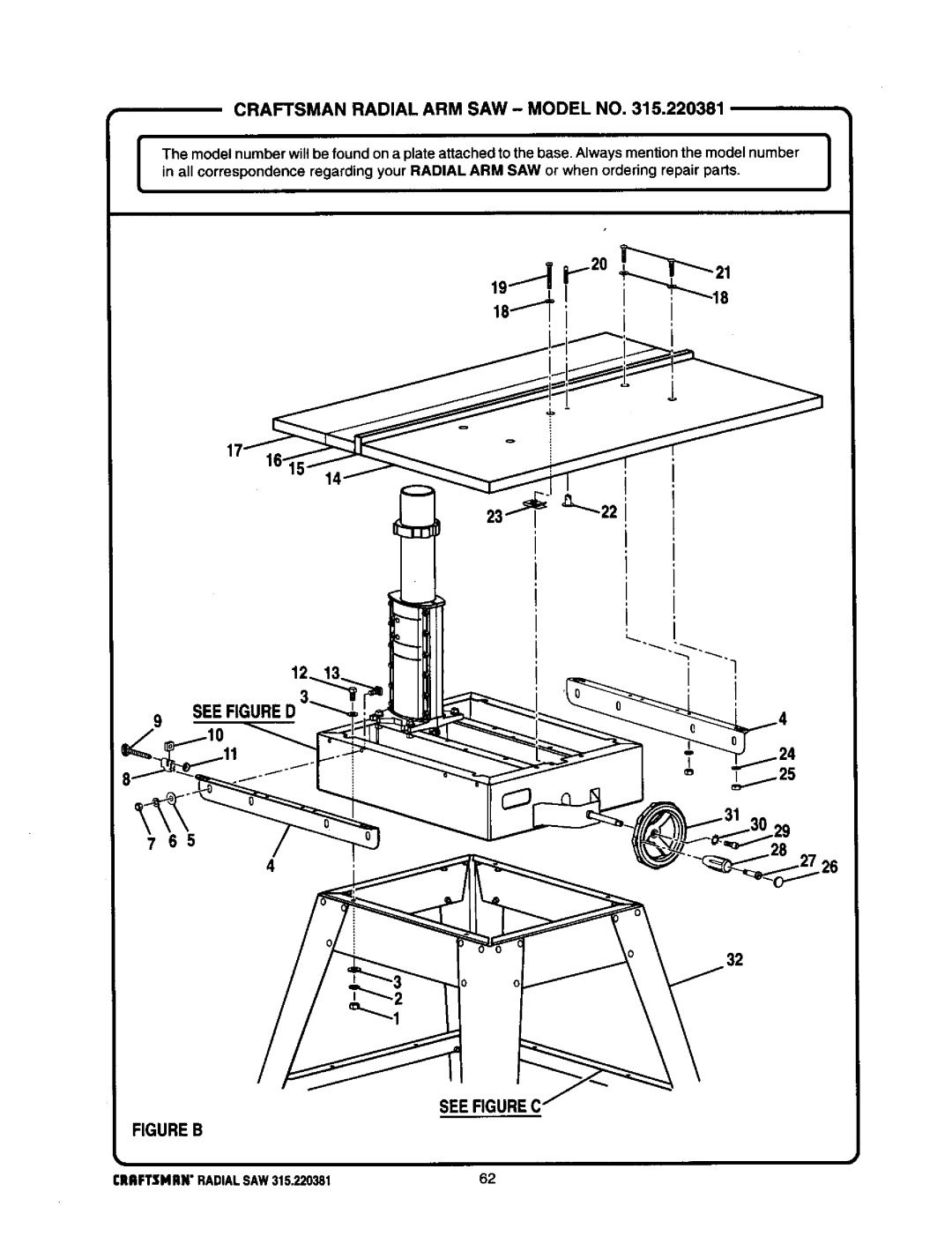
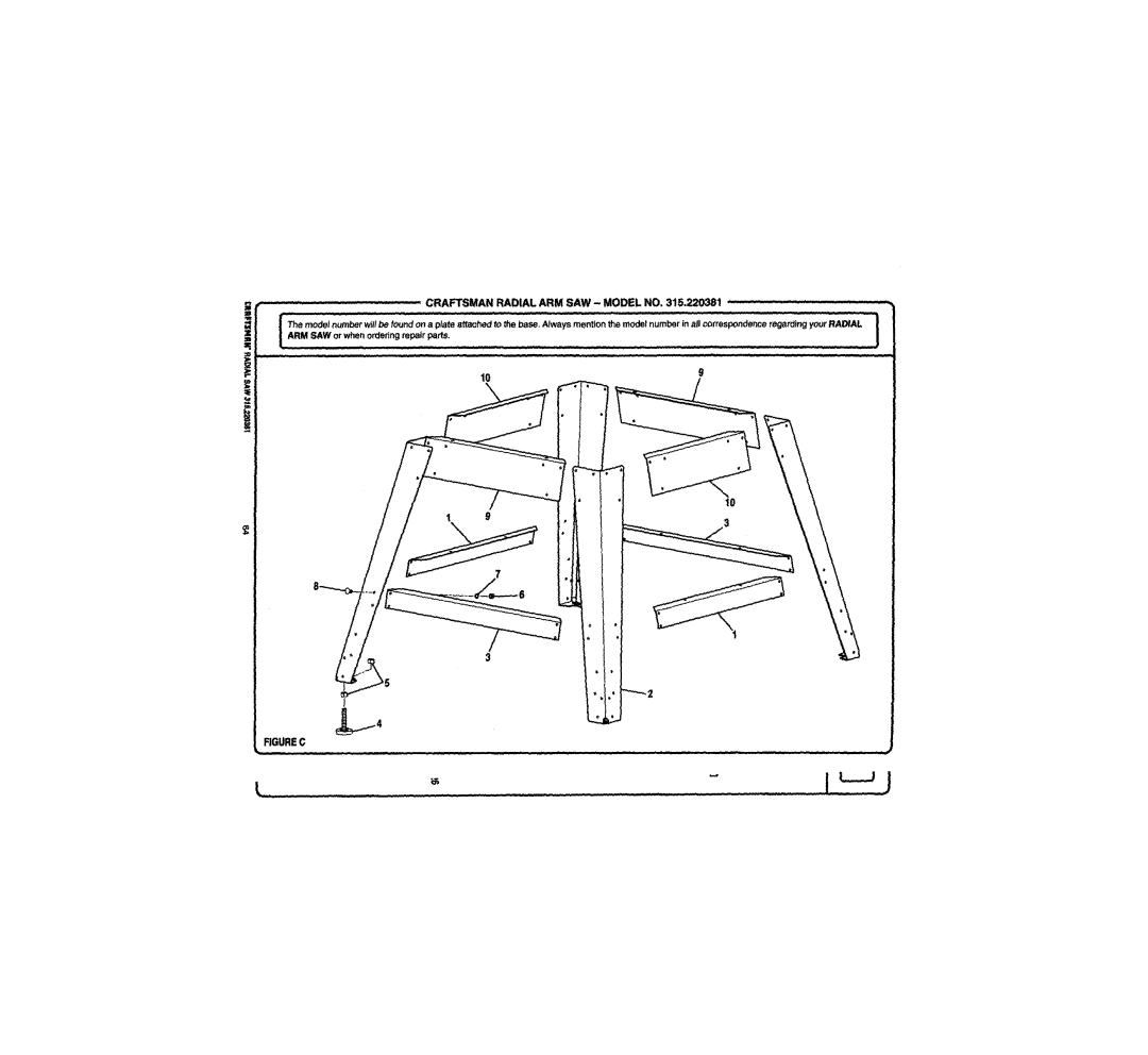
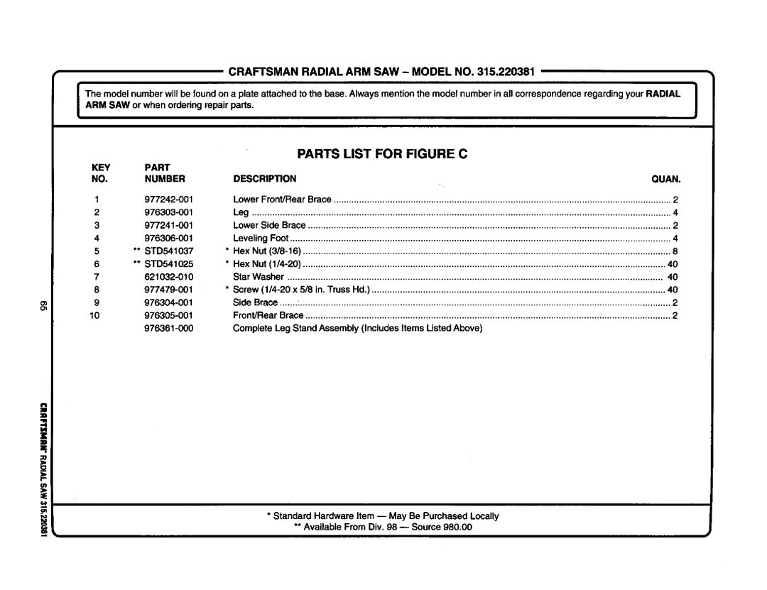
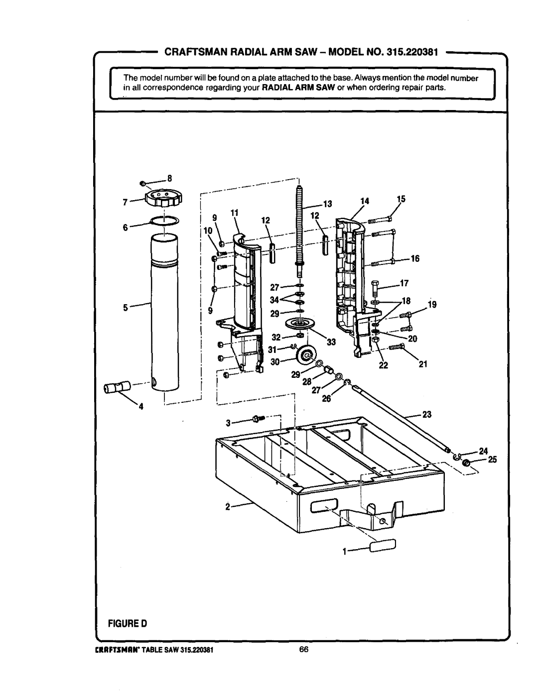
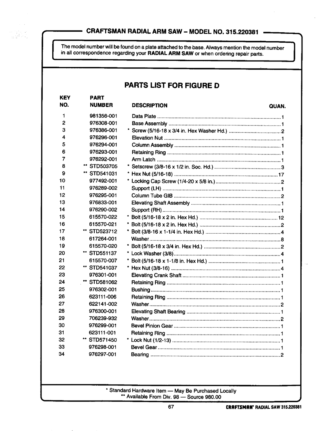
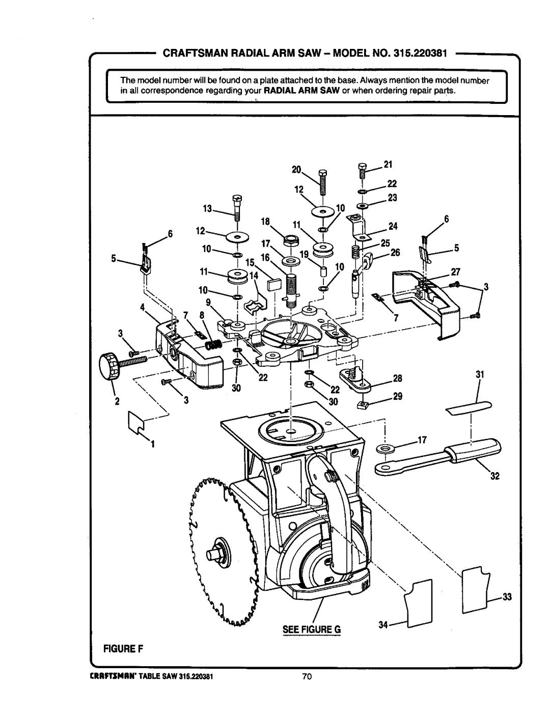
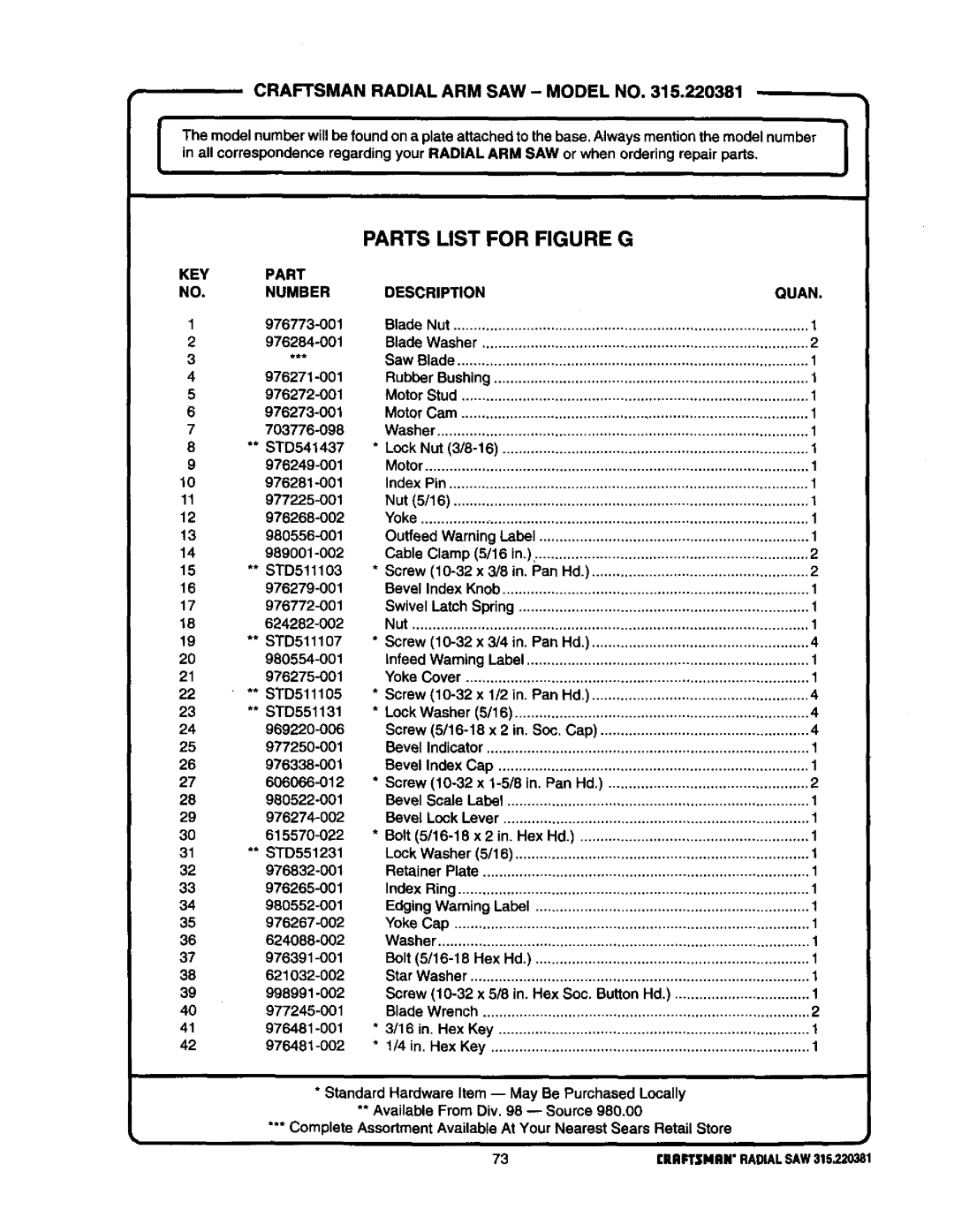
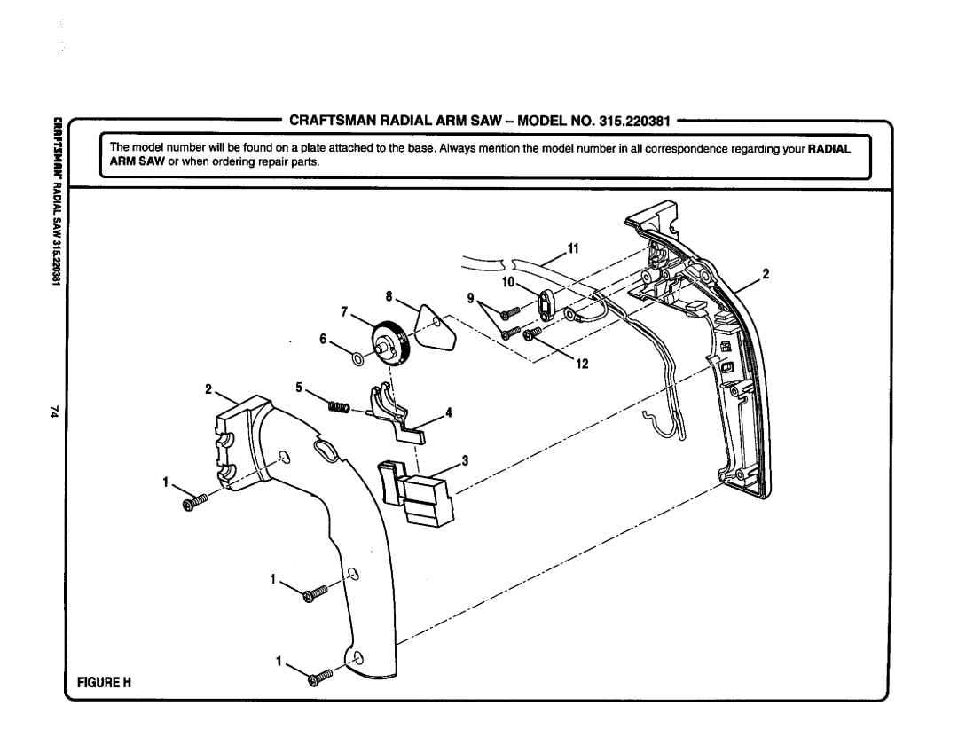
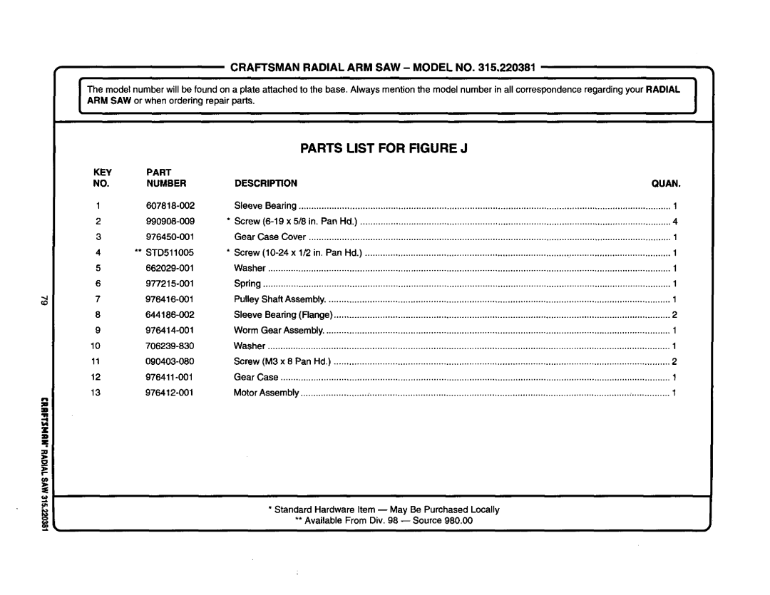
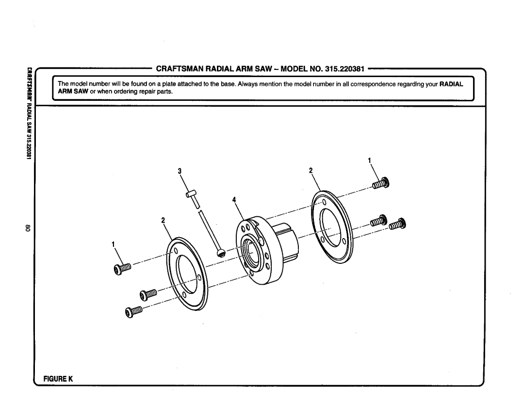
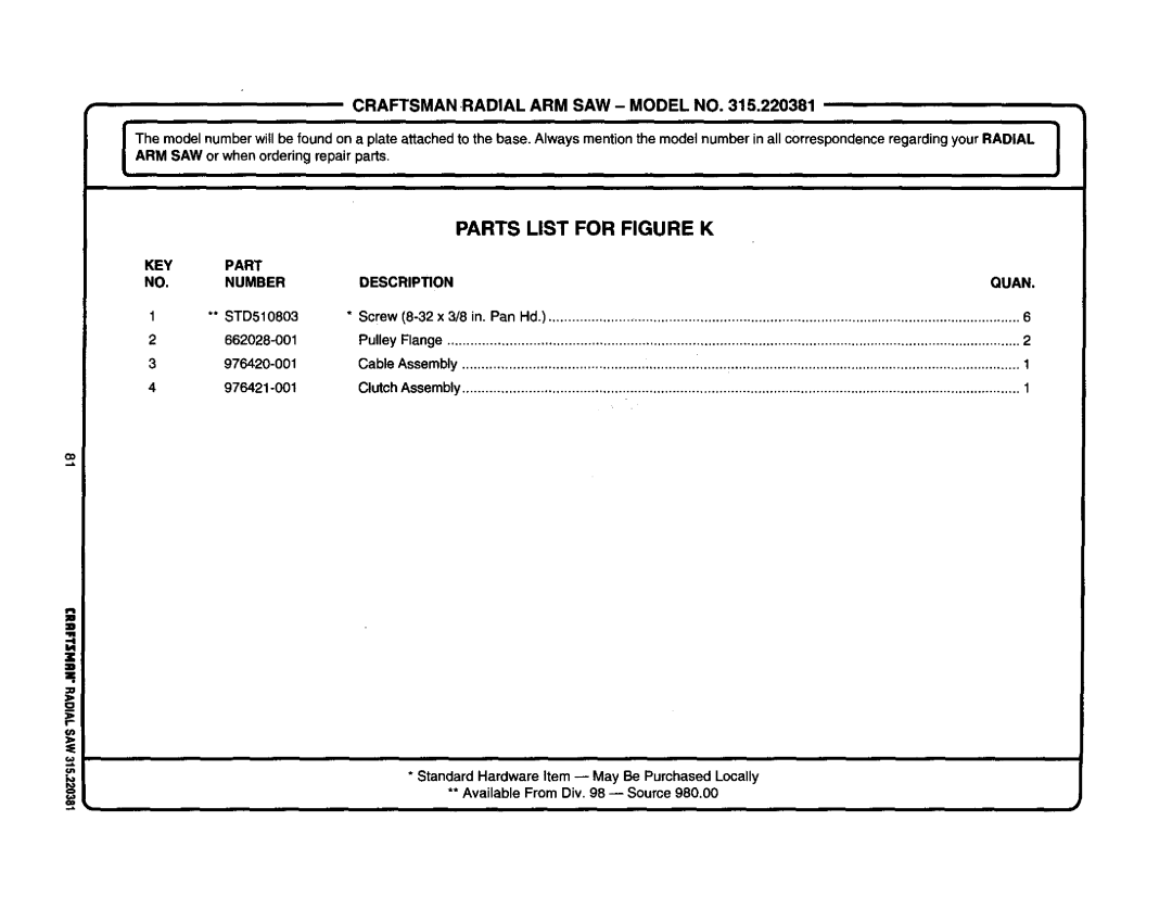
Craftsman 315.220381 owner manual Figurec

Page 64

r"

:::-

_

CRAFTSMAN

RADIAL

ARM SAW -

MODEL NO,, 315.220381

-

....

:

....-

j_ThemI' _de. ARM.numberwSAW_iorbefwhe,und.orderingnap.atearepair_chedtpats_.theba_A_waysmen_i_n_e_num_rin_c_rr_nde_r_rd._rR_AL


=,

.'....

'.'.'.- .

::::: ::::

:

:,

i i:,:::-; : :

::

: ::

::: :

:


10


9


10

1

9

3


7

\

FIGUREC

i

i

i

i

i

i

i

i

iii

ii

iii

i

iiiii

iiiii

i

ii

ii

iii

Image 64
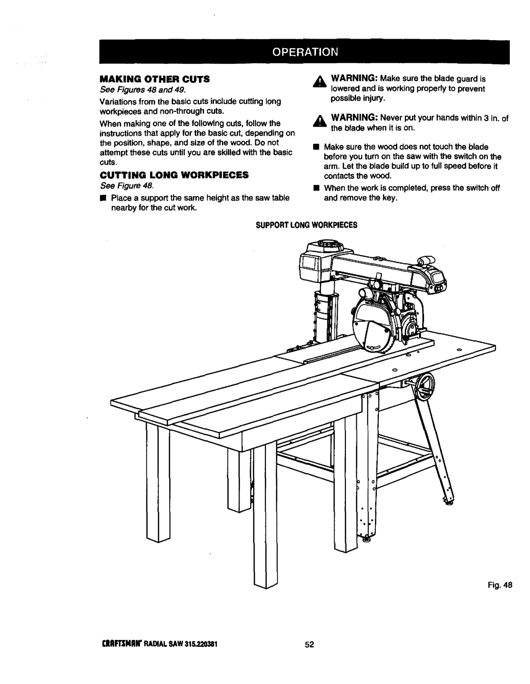
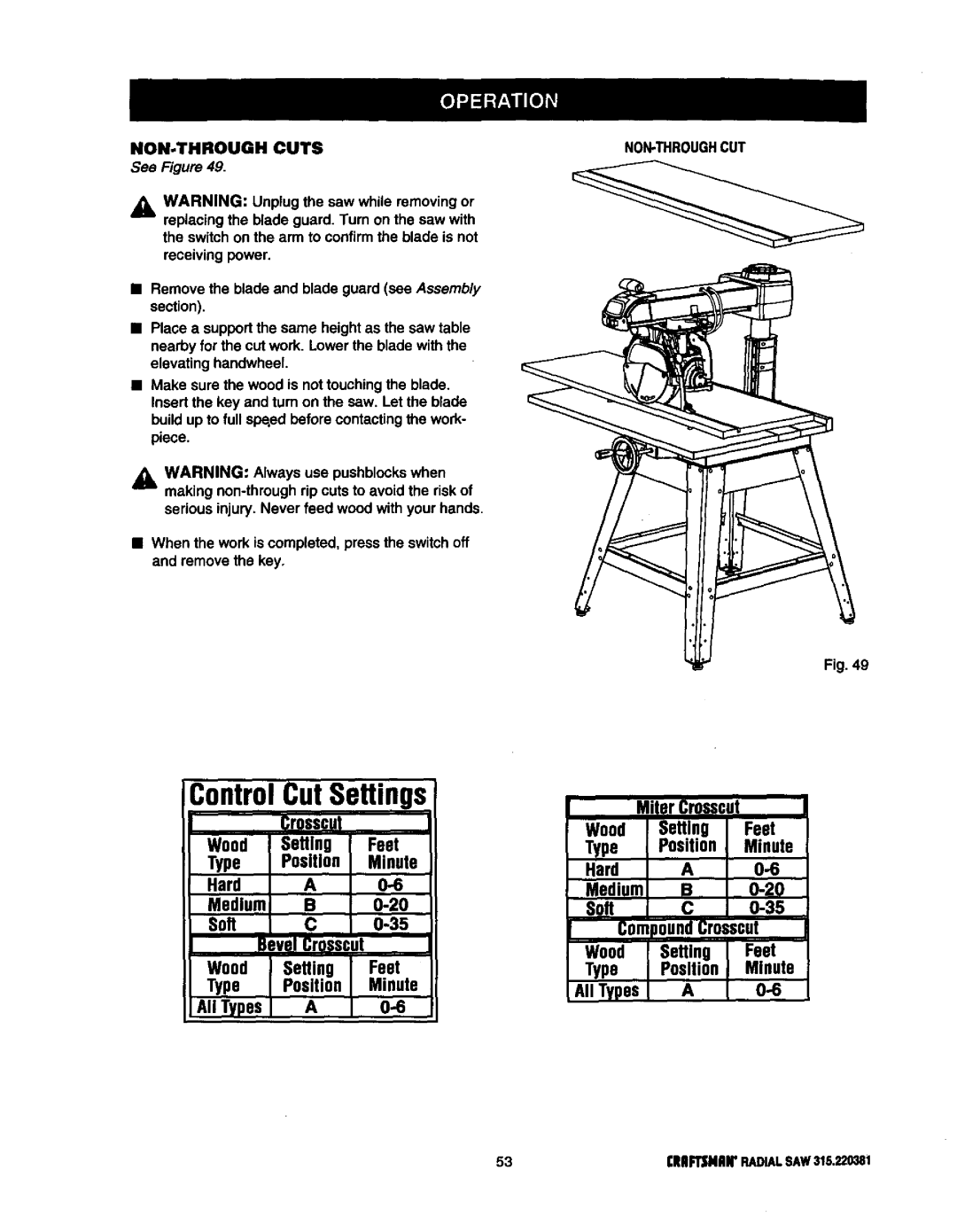
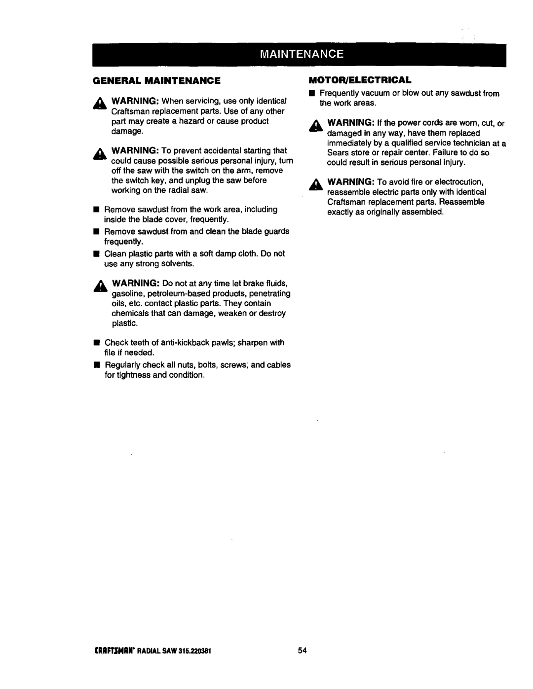
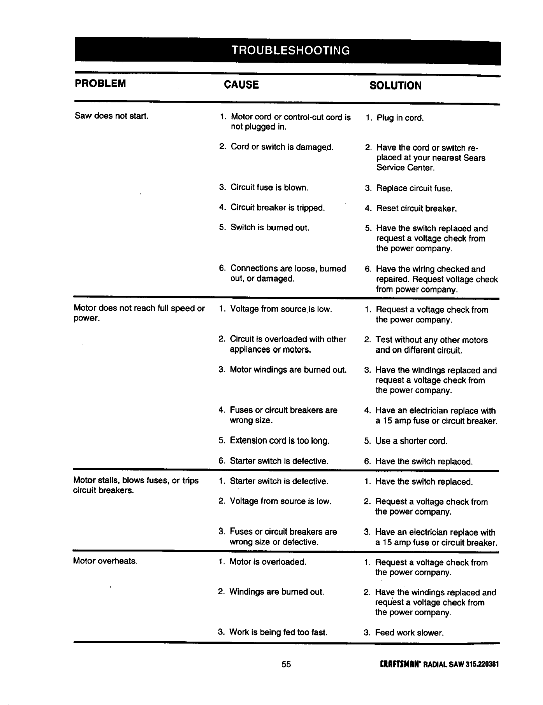
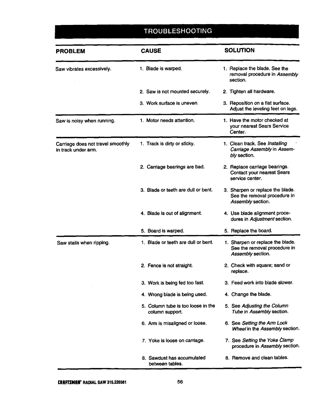
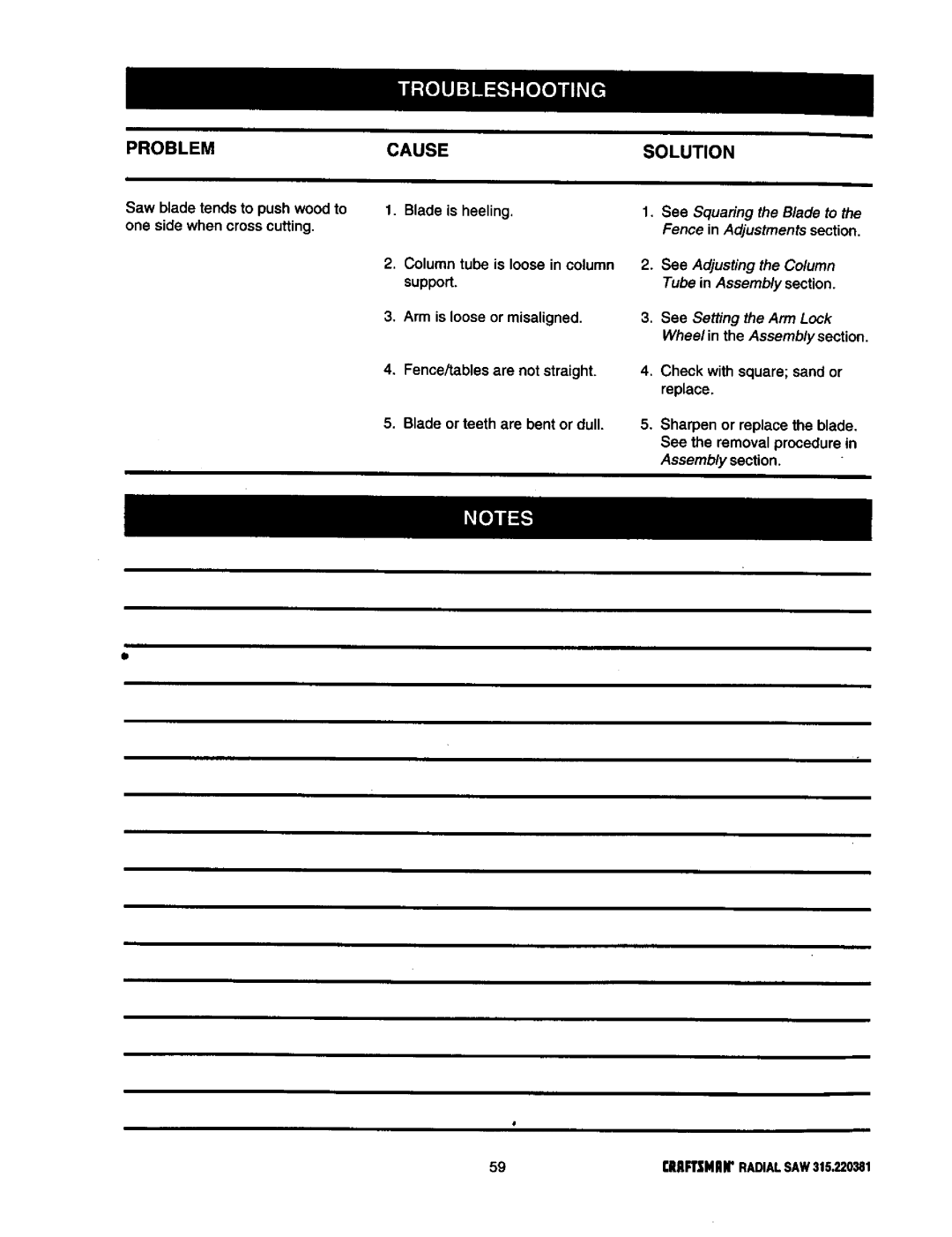
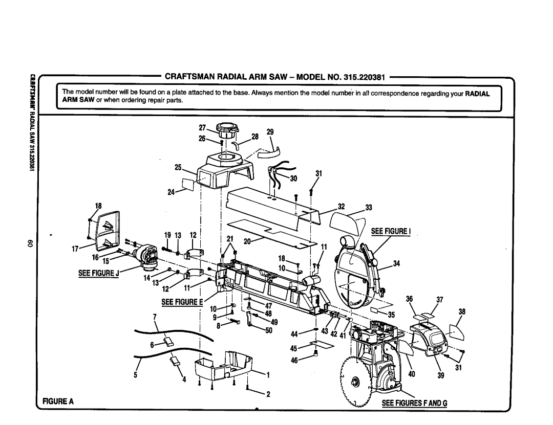
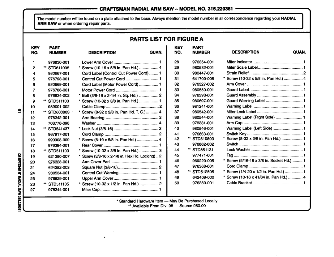
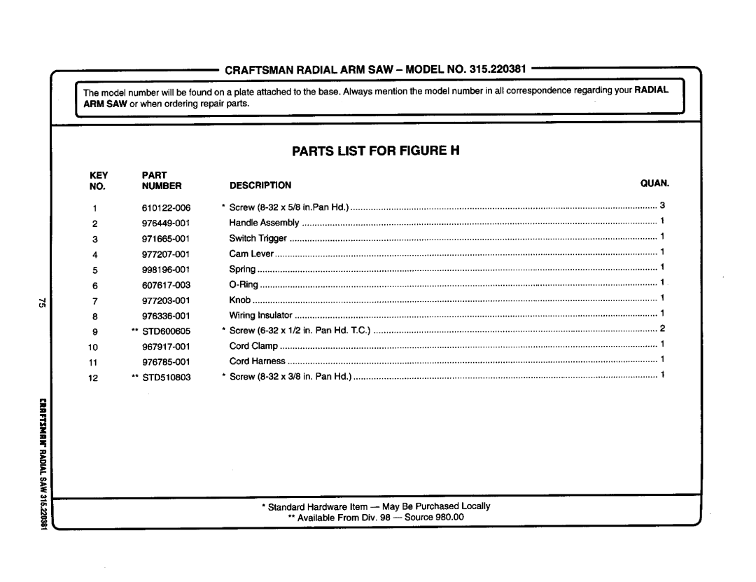
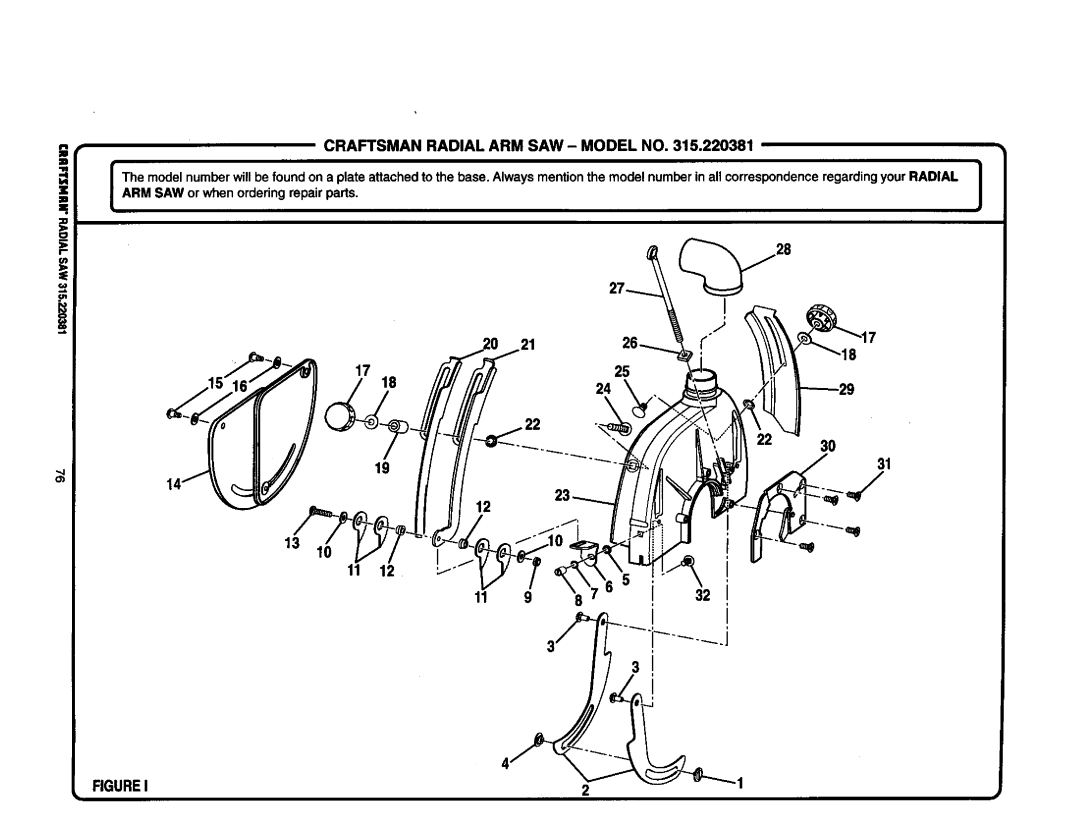
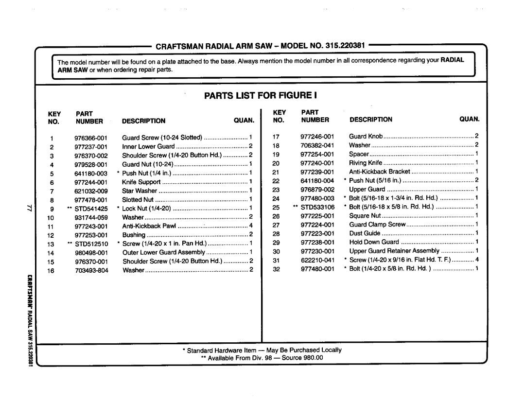
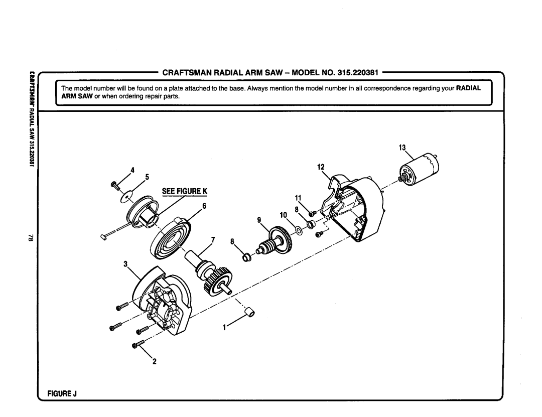
Contents Radial ARM SAW Ofess IonalFull ONE Year Warranty on Craftsman Radial ARM SAW 28-29 Symbol Meaning Safety Alert SymbolAvoid Awkward Operations and Hand Be Sure the Blade Clears the Work RIP only Workpieces Longer than Groundinginstructions Grounding PIN Coverofgrounded OutletboxSee Figures Changing VoltageBladearbor BladeBevelAngle GumRAFTSNANRADIALSAW315,220381 Sawassemblyshownaspacked IIoII Cdef000 Io@C LevelInch Radii Arm Saw RE.ANTPARTSAdvertencia See a KnowyourradialsawYoke Featureslist See Figures 9A-9DMiterscale Armlockknob Yokepivotlatch RIP 19IIRFTSMRNRADIALSAW315.220381Figures 9A and 9B MOTOR13/6.5AMP- Powersthebladeand is Dustguide HolddownAssembly and Adjustments sections before Tighten. See Figure I OASee Figure I OA See Figure lOBMounting SAW to LEG Stand Attaching Elevating Handwheel See FigureSAW Base LEG Sawbase Hexbolt Flat Washer Lockwasher Elevating Shaft Handwheel Screw StarwasherInstalling the Yoke Assembly ArmviewedfrombelowArmlockknob ARM Capscrews Carriagearm LockknobRemoving the Blade Blade Arbor Mounttablesupports UsingtheseholelocationsAttaching Table Supports Setting the ARM Lock Knob Armcap Motor Yokelock Handle AssemblySee Figures 17,4and 17B Yokelock HandleSetting the Bevel Lock Lever Starwasher BevelBevellockleverin Bevel BevelRear Coverscrews HEXBOLT2 HEXNUT2 Adjusting the Column Tube Tightening the ARM and ColumnSee Figures 20A 20D Column ARM Tube SupportElevation Adjustment Rotation AdjustmentColumntube Silverblack Screws ColumnsupportCarriagebearing Adjusting the Carriage BearingsEccentricscrew Wrench Graspandhold Carriagebearing Leveling Table Supports See Figures 22A and 22BBlade Wrenchat Front Armlockknob Rightside TablesupportInstalling the Front Table See Figures 23A 23C23A HexnutSee Figures 25A 25C Leveling the Front TableReartablefence Spacertablefronttable Hole Clamp Bracket SquarenutBlade Rotation Hten WRENCH2 See Figures 27A 27C Carriage Speednut Installing RIP Scale IndicatorsSpring Carriage Screws Lockknob Aligning the ARM for Cross Cuts See Figures 29,4 2gCAligning Blade to Table AT 0 Bevel See Figures 30A 30DIndexcap Bevel Lock Lever Fronttable Socket Elevating Headscrews HandwheelSquaring Blade to Fence See Figures 31A 31CHexbolts Framingsquare YokelockhandleNoadjustment Needed Bevel Adjustment GAPParalleling Blade to Table See Figures 32A-32CIN-RIPSCALEONRIGHTSIDEOFARM RIP-SCALEINDICATOR Aligning the RIP Scale IndicatorsSee Figures 33A 33B Installing Control CUT Device Barrel Carriage Assembly SOCKETF.34Basic Operation of the Radial ARM SAW Types of CutsCross Cuts RIP CutsInsertswitchkey Switchon Switchoff Causes of Kickback Switch and Switch KEYAvoiding Kickback Pushsticks PushblocksFeatnerboards Pushsticks Pushblocks FeatherboardMaking a Cross CUT Carnage Lockknob TableclampsMaking a Miter CUT Making a Bevel CUT Beveledand Elevating Handwheel Making a Compound Cross CUTYoke Armpivotlatch Swwchyokelock Handle Setting UP a RIP CUT RIP CUT Hazards and PrecautionsElevating Handwheel Infeedfor Ripcutting See Figure Review the Hazards and Precautions Making a RIP CUTMaking Other Cuts See Figures 48Cutting Long Workpieces SupportlongworkpiecesNON-THROUGH CutsGeneral Maintenance MOTOR/ELECTRICALProblem Cause SolutionProblem Remove handwheel clean and lubricate the shaft See Adjusting the Column Tube in Assembly sectionAdjustmentssection See Squaring the Blade toFence in Adjustmentssection Cause SolutionAssembly section Seefigure Craftsmanradial ARM SAW- Modelno KEY Part NumberDescription Quan KEY PartFigureb KEY Part NO.NUMBER Craftsman Radial ARM SAW Model no63CRRFTSMRNRADIALSAW315.220381 Figurec Parts List for Figure C Descripon QuanFigured Parts List for Figure D 67CRRFTSNHNRADIALSAW315220381Figuree Parts List for Figure E Figuref See Figure G976287-001 71CRAFTSMANRADIALSAW315.220381See Figure F Seefigureh CRAFTSMANTABLESAW315,22038172Parts List for Figure G 73CRRPTSNRNRADIALSAW315.220381Figureh Parts List for Figure H Descripon OuanFigurei Parts List Craftsmanradial ARM SAW ModelnoFigurej Parts List for Figure J Craftsmanradial ARM SAW- Modelno ,220381Figurek Parts List for Figure K Parts Direct s