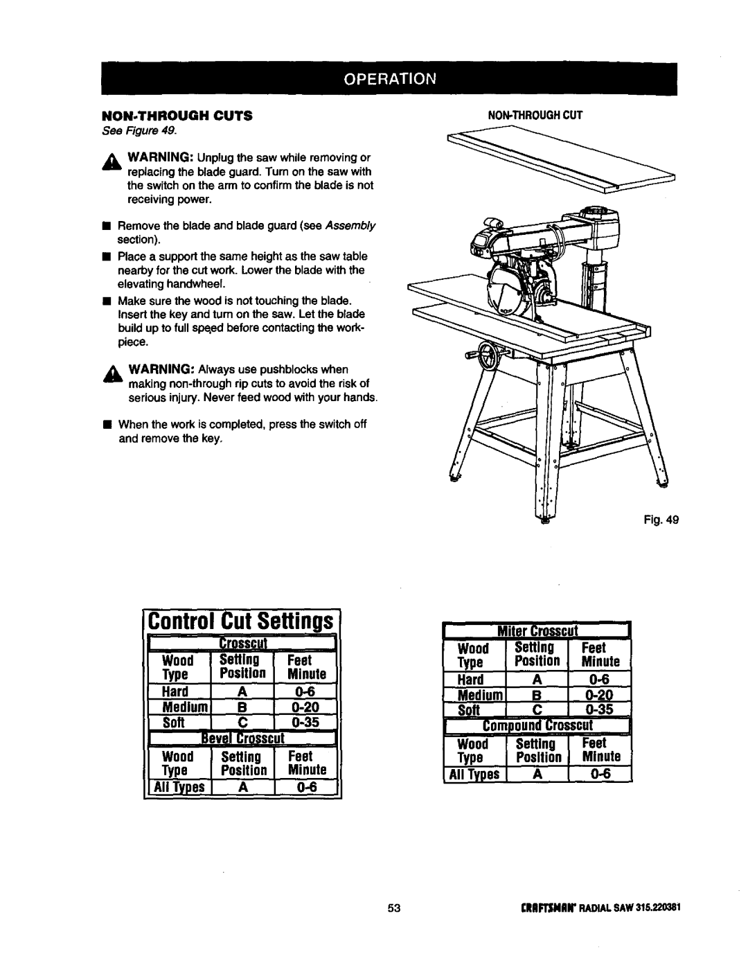
Craftsman 315.220381 owner manual RIP CUT Hazards and Precautions, Setting UP a RIP CUT

Page 50

RIP CUT HAZARDS AND PRECAUTIONS

Two hazards are specificallyassociated with rip cutting:outfeed zone and wrong way feed,

In the ouffeed zone (behind the blade), the blade teeth point down. The slightest contact while the blade is stillspinning can snag clothing, jewelry, the work- piece, or even skin, causing serious personal injury.

Wrong way feed occurs when the workpiece contacts the blade from the ouffeed side. It is very hazardous and willjerk the workpiece violently. You could be cut if you are holding the workpiece.

,_k WARNING: Failure to observe any of these precautions can result in serious injury.

The first precaution is, of course, simply to stay completely away from the ouffeed zone. Keep hands away from the outfeed zone.

Point the anti-kickback pawls away from the blade teeth to snag a workpiece if the blade grabs. They should be positionedto rest lightlyon the workpiece. The flat side of the pawls should be level and horizontal.

Set the riving knife to just clear the table.

Set the hold down in front of the blade to just clear the workpiece.

Start and finish your cut from the infeed side.

Push the workpiece past the pawls with push- blocksand pushsticks to finish the cut.

If the blade jams, turn the saw off with the switch on the arm, remove the yellow key, and wait for the blade to fullystop before freeing it.

Make sure the blade is parallel to the fence and the workpiece is not warped or twisted.

Make sure no pressure is applied to the workpiece on the ouffeed side.

Make sure the blade guard is lowered and is working properly.

Always set up the workpiece so the wider part of the wood is between the blade and the fence. This

stabilizes the workpiece better.

Do not release the workpiece until it has moved past the pawls. Keep pushsticksfirmly in place.

Use pushsUcksand pushblocks, not your hands, when the trailing edge of the workpiece is within

3 in. of the blade. If the blade is set 2 in. or more from the fence, use a pushstiok. Use a pushblock and auxiliary fence when the blade is between 2 in. and 1/2 in. from the fence. (If the cut is narrower than 1/2 in., use a different saw.) For large panel rip cuts, use a featherboard instead of pushblocks or pushsticks.See the section on CuttingAids.

SETTING UP A RIP CUT

See Figure 46.

Aprecise and safe rip cut requires a careful set up. Before setting up for in-rip or out-rip, especially for a bevel cut, try the workpiece in both placements.

Check for stability, visibility,and control. Test which will give the best pushstickclearance.

Instructionsare given for an in-ripcut. At certain points,the instructionswill vary for a bevel rip cut or an out-rip process and will be enclosed in parenthe- ses (example), Figure 47 shows an out-ripsetup.

Insert a solid fence with no kerfs. Use an auxiliary fence if the blade will be set only 1/2 in. to 2 in. from the fence. Tighten the table clamps,

If the arm is too low or too high, first liftthe blade

guard if the arm is too low, and turn the elevating handwheel at the front of the table. Set the blade to

just clear the kerf or table.

Change the blade angle if needed. Raise the plastic lower guard to keep it from jamming, release the bevel lock lever, and set the bevel indicatorto zero. (For a bevel rip cut, set the bevel Indicator to the desired angle.) Test the clearance on the guard. Retighten the bevel lock lever.

ELEVATING

HANDWHEEL

INFEEDFOR

IN RIPCUTTING

Fig. 46

I'IIIIFTSMIIIPRADIALSAW 315.22038150
Image 50
Contents Radial ARM SAW Ofess IonalFull ONE Year Warranty on Craftsman Radial ARM SAW 28-29 Symbol Meaning Safety Alert SymbolAvoid Awkward Operations and Hand Be Sure the Blade Clears the Work RIP only Workpieces Longer than Groundinginstructions Grounding PIN Coverofgrounded OutletboxBladearbor Changing VoltageSee Figures BladeBevelAngle GumRAFTSNANRADIALSAW315,220381 Sawassemblyshownaspacked IIoII Cdef000 Io@C LevelInch Radii Arm Saw RE.ANTPARTSAdvertencia Yoke KnowyourradialsawSee a Miterscale Armlockknob Yokepivotlatch RIP FeatureslistSee Figures 9A-9D 19IIRFTSMRNRADIALSAW315.220381Figures 9A and 9B MOTOR13/6.5AMP- Powersthebladeand is Dustguide HolddownSee Figure I OA Assembly and Adjustments sections beforeTighten. See Figure I OA See Figure lOBSAW Base LEG Sawbase Hexbolt Flat Washer Lockwasher Mounting SAW to LEG Stand Attaching Elevating HandwheelSee Figure Elevating Shaft Handwheel Screw StarwasherArmlockknob ARM Capscrews Installing the Yoke AssemblyArmviewedfrombelow Carriagearm LockknobAttaching Table Supports Blade Arbor Mounttablesupports UsingtheseholelocationsRemoving the Blade See Figures 17,4and 17B Setting the ARM Lock KnobArmcap Motor Yokelock Handle Assembly Yokelock HandleBevellockleverin Setting the Bevel Lock LeverStarwasher Bevel Bevel BevelSee Figures 20A 20D Rear Coverscrews HEXBOLT2 HEXNUT2 Adjusting the Column TubeTightening the ARM and Column Column ARM Tube SupportColumntube Elevation AdjustmentRotation Adjustment Silverblack Screws ColumnsupportEccentricscrew Wrench Graspandhold Carriagebearing Adjusting the Carriage BearingsCarriagebearing Blade Wrenchat Front Armlockknob Leveling Table SupportsSee Figures 22A and 22B Rightside Tablesupport23A Installing the Front TableSee Figures 23A 23C HexnutReartablefence Spacertablefronttable Leveling the Front TableSee Figures 25A 25C Blade Rotation Hten WRENCH2 Clamp Bracket SquarenutHole See Figures 27A 27C Spring Carriage Screws Lockknob Installing RIP Scale IndicatorsCarriage Speednut Aligning the ARM for Cross Cuts See Figures 29,4 2gCIndexcap Bevel Aligning Blade to Table AT 0 BevelSee Figures 30A 30D Lock Lever Fronttable Socket Elevating Headscrews HandwheelHexbolts Squaring Blade to FenceSee Figures 31A 31C Framingsquare YokelockhandleParalleling Blade to Table Noadjustment Needed BevelAdjustment GAP See Figures 32A-32CSee Figures 33A 33B Aligning the RIP Scale IndicatorsIN-RIPSCALEONRIGHTSIDEOFARM RIP-SCALEINDICATOR Installing Control CUT Device Barrel Carriage Assembly SOCKETF.34Cross Cuts Basic Operation of the Radial ARM SAWTypes of Cuts RIP CutsAvoiding Kickback Switch and Switch KEYInsertswitchkey Switchon Switchoff Causes of Kickback Featnerboards PushsticksPushblocks Pushsticks Pushblocks FeatherboardMaking a Cross CUT Carnage Lockknob TableclampsMaking a Miter CUT Making a Bevel CUT Yoke Armpivotlatch Swwchyokelock Handle Making a Compound Cross CUTBeveledand Elevating Handwheel Elevating Handwheel Infeedfor Ripcutting RIP CUT Hazards and PrecautionsSetting UP a RIP CUT See Figure Review the Hazards and Precautions Making a RIP CUTCutting Long Workpieces Making Other CutsSee Figures 48 SupportlongworkpiecesNON-THROUGH CutsGeneral Maintenance MOTOR/ELECTRICALProblem Cause SolutionProblem Remove handwheel clean and lubricate the shaft Adjustmentssection See Adjusting the ColumnTube in Assembly section See Squaring the Blade toAssembly section Cause SolutionFence in Adjustmentssection Seefigure Description Quan Craftsmanradial ARM SAW- ModelnoKEY Part Number KEY PartFigureb 63CRRFTSMRNRADIALSAW315.220381 Craftsman Radial ARM SAW Model noKEY Part NO.NUMBER Figurec Parts List for Figure C Descripon QuanFigured Parts List for Figure D 67CRRFTSNHNRADIALSAW315220381Figuree Parts List for Figure E Figuref See Figure G976287-001 71CRAFTSMANRADIALSAW315.220381See Figure F Seefigureh CRAFTSMANTABLESAW315,22038172Parts List for Figure G 73CRRPTSNRNRADIALSAW315.220381Figureh Parts List for Figure H Descripon OuanFigurei Parts List Craftsmanradial ARM SAW ModelnoFigurej Parts List for Figure J Craftsmanradial ARM SAW- Modelno ,220381Figurek Parts List for Figure K Parts Direct s