Craftsman 315.220381 owner manual Avoid Awkward Operations and Hand

Page 5

USE THE PROPER EXTENSION CORD. Make

sure your extension cord is in good condition, Use only a cord heavy enough to carry the current your product will draw. An undersized cord will cause a drop in line voltage resulting in loss of power and overheating. A wire gage size (A.W.G.) of at least 14 is recommended for an extension cord 25 feet

or less in length. If in doubt, use the next heavier

gage. The smaller the gage number, the heavier the cord,

AVOID ACCIDENTAL STARTING. Be sure switch is off when plugging in the tool.

REMOVE WRENCHES AND ADJUSTING KEYS. Get in the habit of checking - before turning on the tool - that hex keys and adjusting wrenches are removed from tool.

CHECK DAMAGED PARTS. Before using the tool again, check any damaged parts, including guards, for proper operation and performance. Check alignment of moving parts, bindingof moving parts, breakage of parts, saw stability, mounting,and any other conditionsthat may affect its operation. A damaged part must be properly repaired or re- placed by a qualified service technician at a Sears repair center to avoid risk of personal injury.
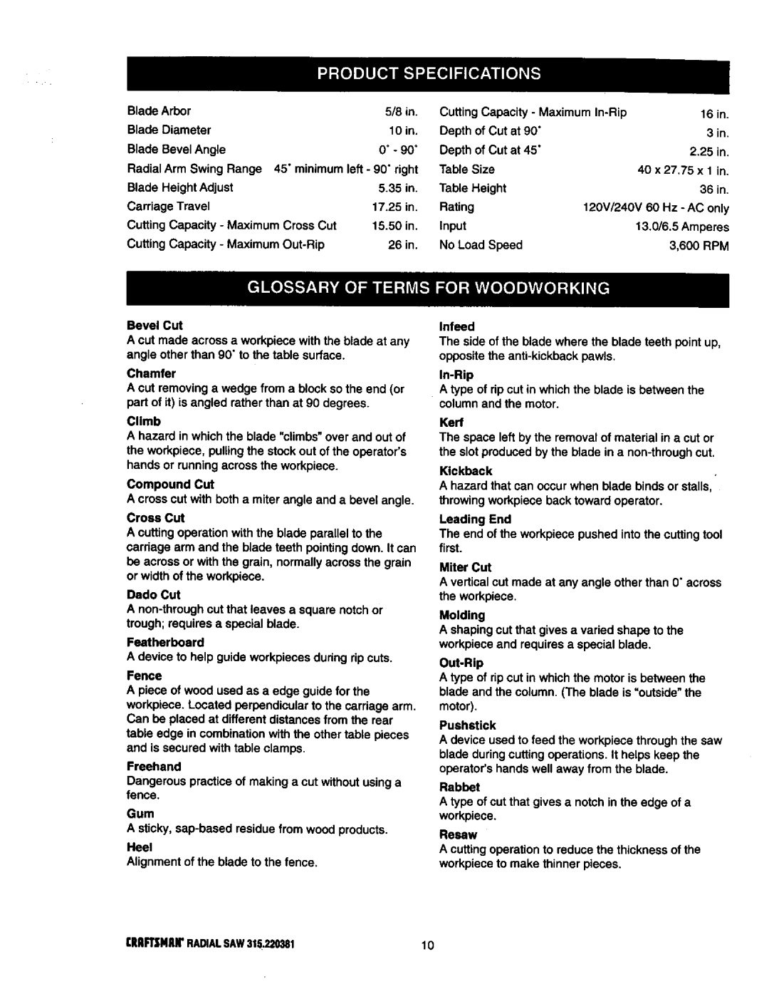
USE ONLY CORRECT BLADES. Use the right blade style for the material and the type of cut. Use only blades marked for at least 5,000 rpm and 10 in. or smaller, with a 5/8 in. arbor hole.

KEEP GUARDS IN PLACE and in good working

order. This includes the blade guard, the riving knife, and the anti-kickback pawls.

CHECK DIRECTION OF FEED. When ripping,

feed work into a blade or cutter against the direc- tion of rotationof the blade or cutter.

NEVER LEAVE TOOL RUNNING UNA'I'rENDED. TURN THE POWER OFF. Do not leave the tool until it comes to a complete stop.

USE RECOMMENDED ACCESSORIES. Using improper accessories may risk injury. Consult the Accessories section for recommended acceSso- ries.

USE ONLY SEARS REPLACEMENT PARTS. All

repairs, whether electrical or mechanical, should be made by a qualified service technician at a Sears repair center.

DISCONNECT ALL TOOLS. When not in use, before servicing, or when changing attachments, blades, bits, cutters, etc., all tools should be disconnected from the power supply.

DO NOT FORCE THE TOOL. It will do the job better and moresafely at the rate for which it was designed.

BEFORE MOUNTING, DISCONNECTING OR REMOUNTING THE MOTOR; unplug the saw and remove the switch key.

_l, WARNING: When servicing, use only identical

Craftsman replacement pads. Use of any other parts may create a hazard or damage product.

NEVER USE THIS TOOL IN AN EXPLOSIVE ATMOSPHERE. Normal sparking of the motor could ignite fumes.

MAKE SURE THE WORK AREA HAS AMPLE LIGHTING to see the work and that no obstruc- tions will interfere with safe operation BEFORE performing any work using this tool.

DO NOT USE TOOL IF SWITCH DOES NOT TURN IT ON AND OFF. Have defective switches replaced by a qualified service technician at a

Sears repair center.

GUARD AGAINST ELECTRICAL SHOCK by preventing body contact with grounded surfaces

such as pipes, radiators, ranges, refrigerator enclosures.

GROUND ALL TOOLS. See Electrical page.

WEAR A DUST MASK to keep from inhaling fine particles. Use wood dust collection systems whenever possible.

PROTECT YOUR HEARING. Wear hearing protectionduring extended periods of operation.

DO NOT OPERATE THIS TOOL WHILE UNDER

THE INFLUENCE OF DRUGS, ALCOHOL, OR ANY MEDICATION.

STAY ALERT AND EXERCISE CONTROL. Watch what you are doing and use common sense. Do not operate tool when you are tired. Do not rush.

AVOID AWKWARD OPERATIONS AND HAND

POSITIONS where a sudden slip could cause your hand to move into the blade, ALWAYS make sure

you have good balance•

5

qlIIFt3NlUr RADIALSAW$15.220_t

Image 5
Contents Ofess Ional Radial ARM SAWFull ONE Year Warranty on Craftsman Radial ARM SAW 28-29 Meaning Safety Alert Symbol SymbolAvoid Awkward Operations and Hand Be Sure the Blade Clears the Work RIP only Workpieces Longer than Grounding PIN Coverofgrounded Outletbox GroundinginstructionsBladearbor Changing VoltageSee Figures Gum BladeBevelAngleRAFTSNANRADIALSAW315,220381 Sawassemblyshownaspacked Cdef IIoII000 Level Io@CRE.ANTPARTS Inch Radii Arm SawAdvertencia Yoke KnowyourradialsawSee a See Figures 9A-9D FeatureslistMiterscale Armlockknob Yokepivotlatch RIP 19IIRFTSMRNRADIALSAW315.220381Figures 9A and 9B Dustguide Holddown MOTOR13/6.5AMP- Powersthebladeand isTighten. See Figure I OA Assembly and Adjustments sections beforeSee Figure I OA See Figure lOBSee Figure Mounting SAW to LEG Stand Attaching Elevating HandwheelSAW Base LEG Sawbase Hexbolt Flat Washer Lockwasher Elevating Shaft Handwheel Screw StarwasherArmviewedfrombelow Installing the Yoke AssemblyArmlockknob ARM Capscrews Carriagearm LockknobAttaching Table Supports Blade Arbor Mounttablesupports UsingtheseholelocationsRemoving the Blade Armcap Motor Yokelock Handle Assembly Setting the ARM Lock KnobSee Figures 17,4and 17B Yokelock HandleStarwasher Bevel Setting the Bevel Lock LeverBevellockleverin Bevel BevelTightening the ARM and Column Rear Coverscrews HEXBOLT2 HEXNUT2 Adjusting the Column TubeSee Figures 20A 20D Column ARM Tube SupportRotation Adjustment Elevation AdjustmentColumntube Silverblack Screws ColumnsupportEccentricscrew Wrench Graspandhold Carriagebearing Adjusting the Carriage BearingsCarriagebearing See Figures 22A and 22B Leveling Table SupportsBlade Wrenchat Front Armlockknob Rightside TablesupportSee Figures 23A 23C Installing the Front Table23A HexnutReartablefence Spacertablefronttable Leveling the Front TableSee Figures 25A 25C Blade Rotation Hten WRENCH2 Clamp Bracket SquarenutHole See Figures 27A 27C Spring Carriage Screws Lockknob Installing RIP Scale IndicatorsCarriage Speednut See Figures 29,4 2gC Aligning the ARM for Cross CutsSee Figures 30A 30D Aligning Blade to Table AT 0 BevelIndexcap Bevel Lock Lever Fronttable Socket Elevating Headscrews HandwheelSee Figures 31A 31C Squaring Blade to FenceHexbolts Framingsquare YokelockhandleAdjustment GAP Noadjustment Needed BevelParalleling Blade to Table See Figures 32A-32CSee Figures 33A 33B Aligning the RIP Scale IndicatorsIN-RIPSCALEONRIGHTSIDEOFARM RIP-SCALEINDICATOR Barrel Carriage Assembly SOCKETF.34 Installing Control CUT DeviceTypes of Cuts Basic Operation of the Radial ARM SAWCross Cuts RIP CutsAvoiding Kickback Switch and Switch KEYInsertswitchkey Switchon Switchoff Causes of Kickback Pushblocks PushsticksFeatnerboards Pushsticks Pushblocks FeatherboardCarnage Lockknob Tableclamps Making a Cross CUTMaking a Miter CUT Making a Bevel CUT Yoke Armpivotlatch Swwchyokelock Handle Making a Compound Cross CUTBeveledand Elevating Handwheel Elevating Handwheel Infeedfor Ripcutting RIP CUT Hazards and PrecautionsSetting UP a RIP CUT Making a RIP CUT See Figure Review the Hazards and PrecautionsSee Figures 48 Making Other CutsCutting Long Workpieces SupportlongworkpiecesCuts NON-THROUGHMOTOR/ELECTRICAL General MaintenanceSolution Problem CauseProblem Remove handwheel clean and lubricate the shaft Tube in Assembly section See Adjusting the ColumnAdjustmentssection See Squaring the Blade toAssembly section Cause SolutionFence in Adjustmentssection Seefigure KEY Part Number Craftsmanradial ARM SAW- ModelnoDescription Quan KEY PartFigureb 63CRRFTSMRNRADIALSAW315.220381 Craftsman Radial ARM SAW Model noKEY Part NO.NUMBER Figurec Descripon Quan Parts List for Figure CFigured 67CRRFTSNHNRADIALSAW315220381 Parts List for Figure DFiguree Parts List for Figure E See Figure G Figuref71CRAFTSMANRADIALSAW315.220381 976287-001CRAFTSMANTABLESAW315,22038172 See Figure F Seefigureh73CRRPTSNRNRADIALSAW315.220381 Parts List for Figure GFigureh Descripon Ouan Parts List for Figure HFigurei Craftsmanradial ARM SAW Modelno Parts ListFigurej Craftsmanradial ARM SAW- Modelno ,220381 Parts List for Figure JFigurek Parts List for Figure K Parts Direct s