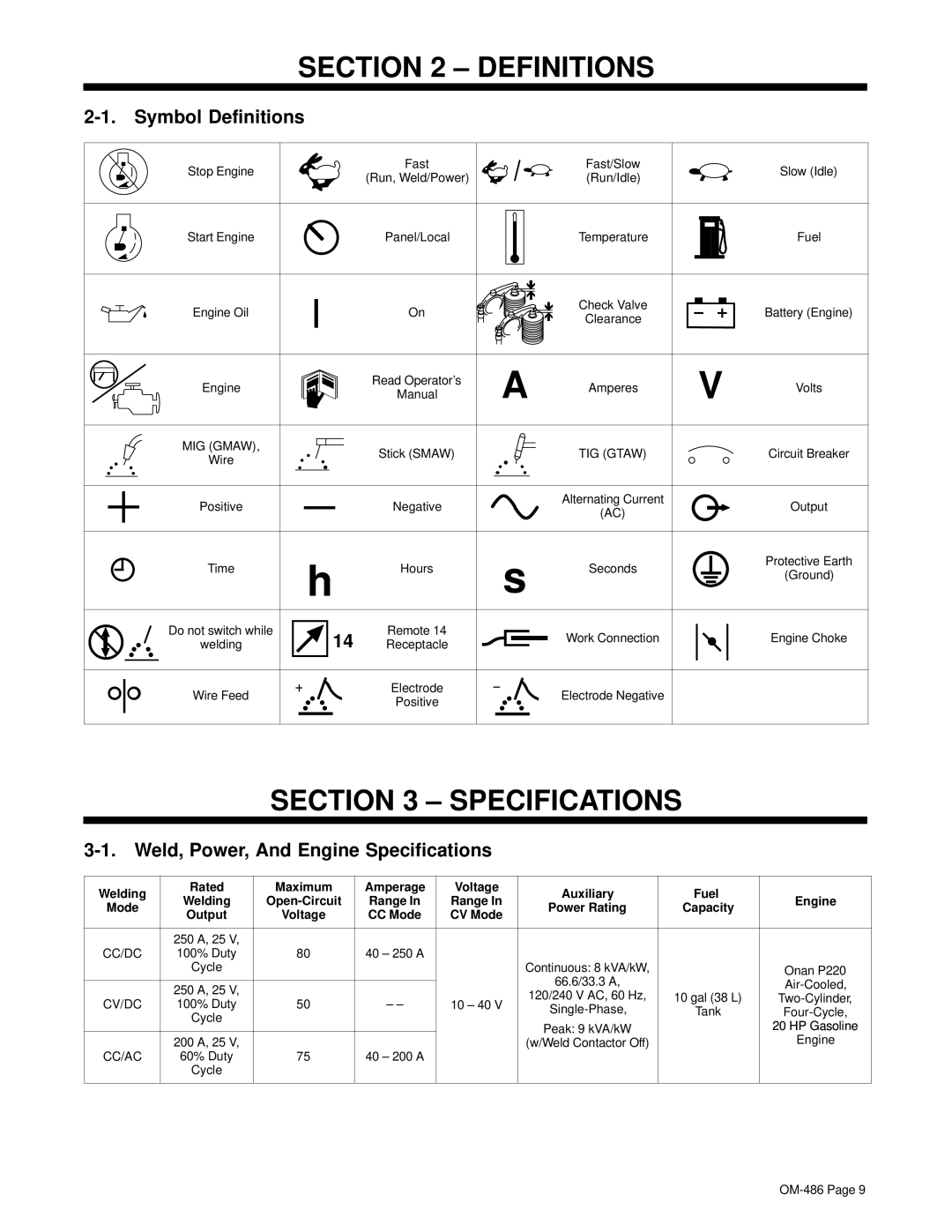
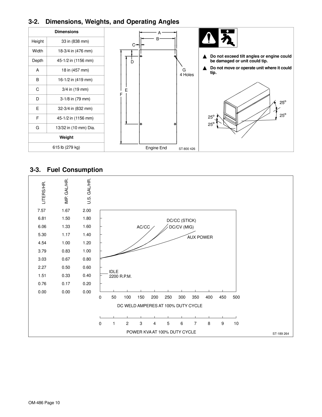
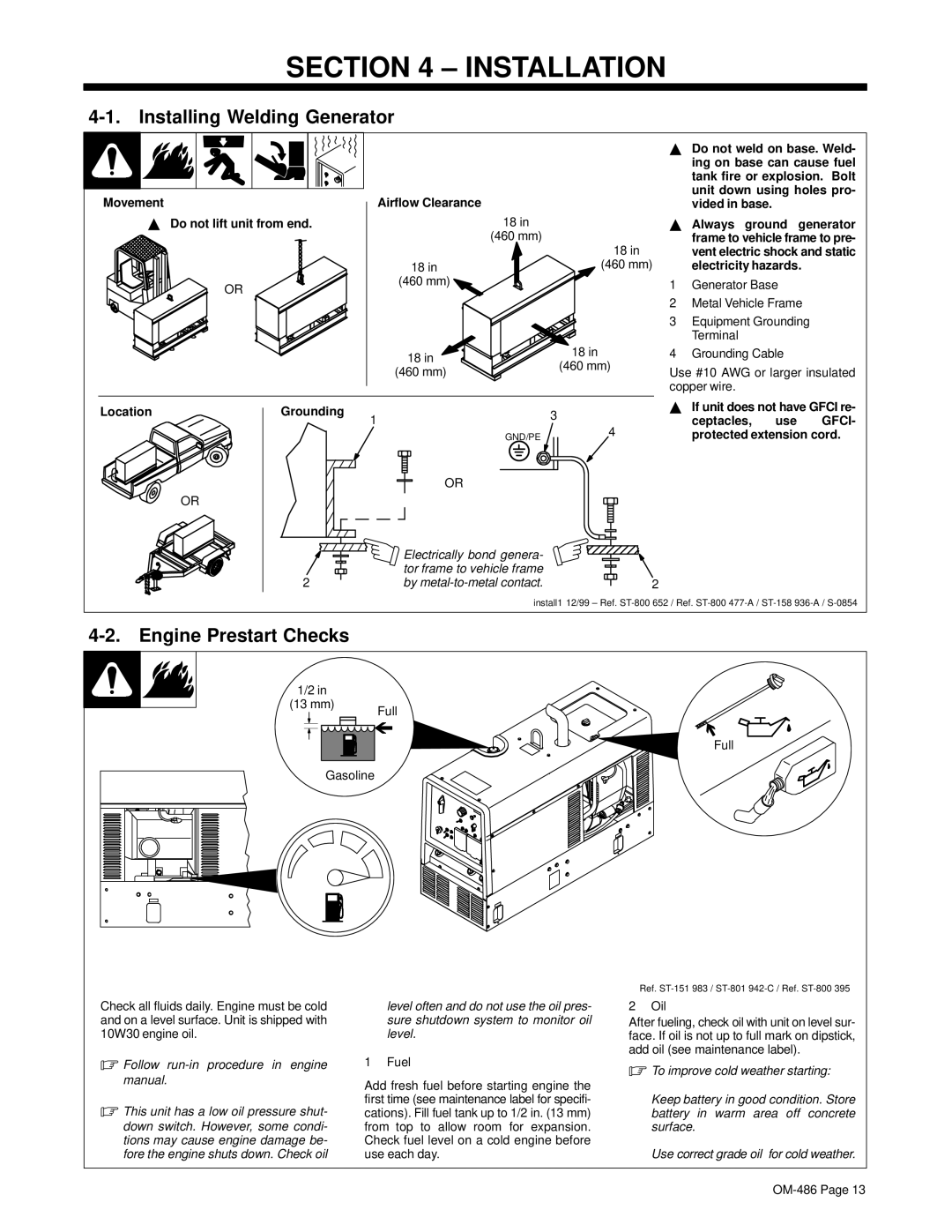
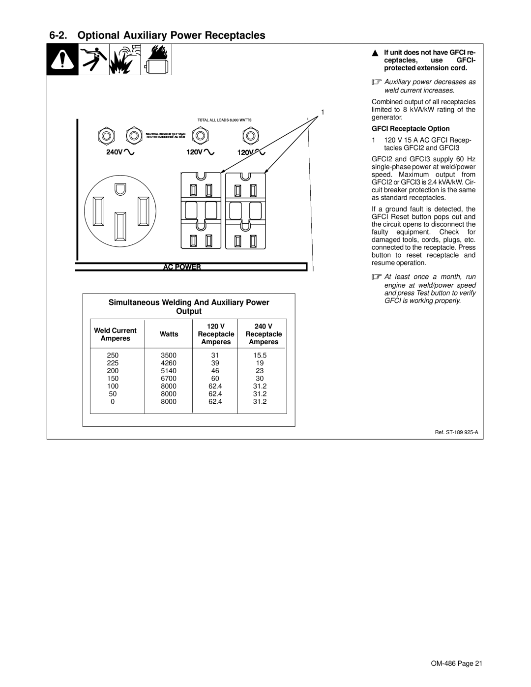
4-9. Adjusting MIG Weld Puddle Consistency
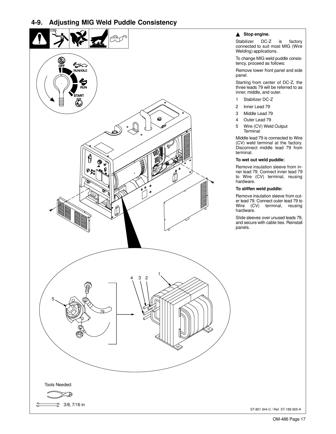
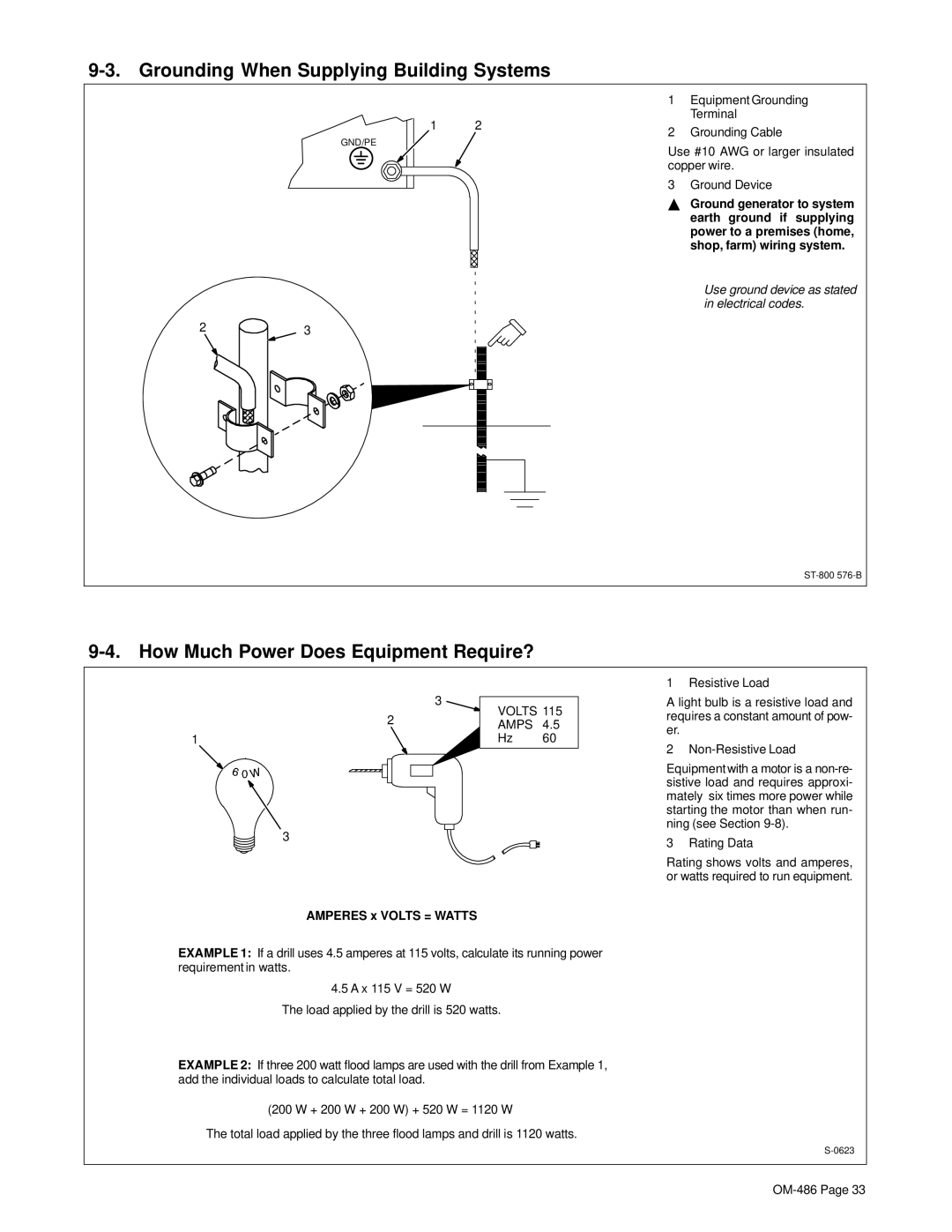
Y Stop engine.
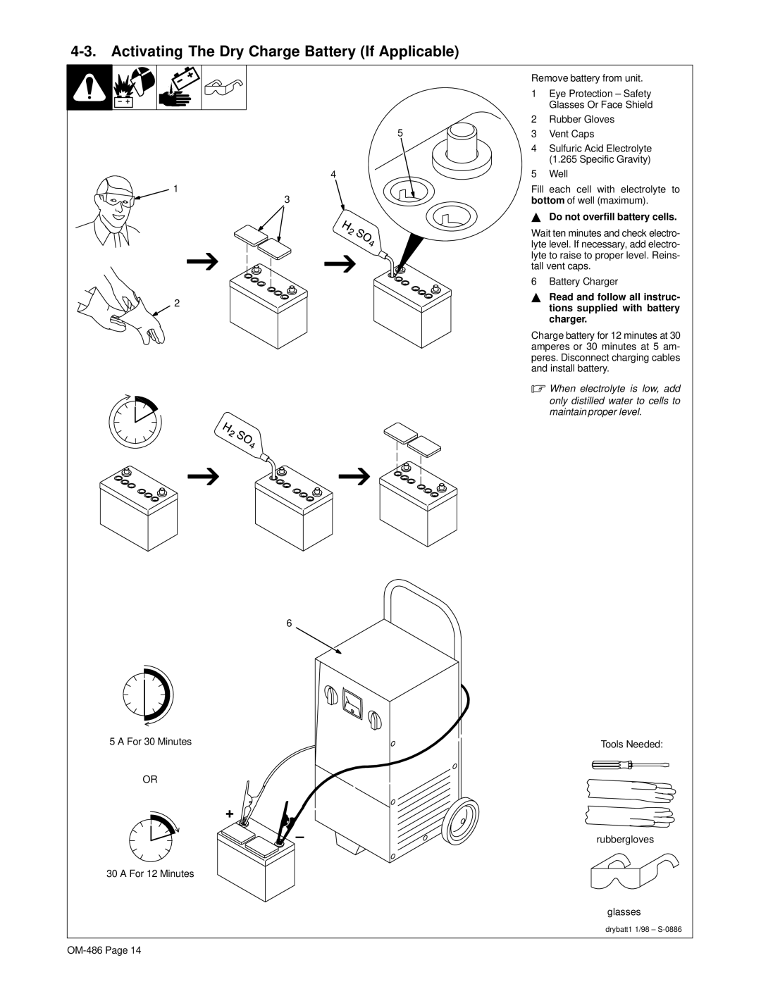
Stabilizer
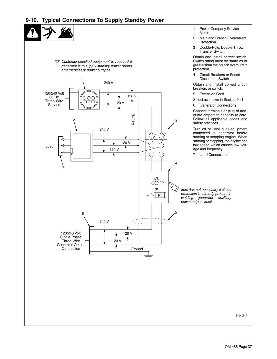
To change MIG weld puddle consis- tency, proceed as follows:
Remove lower front panel and side panel.
Starting from center of
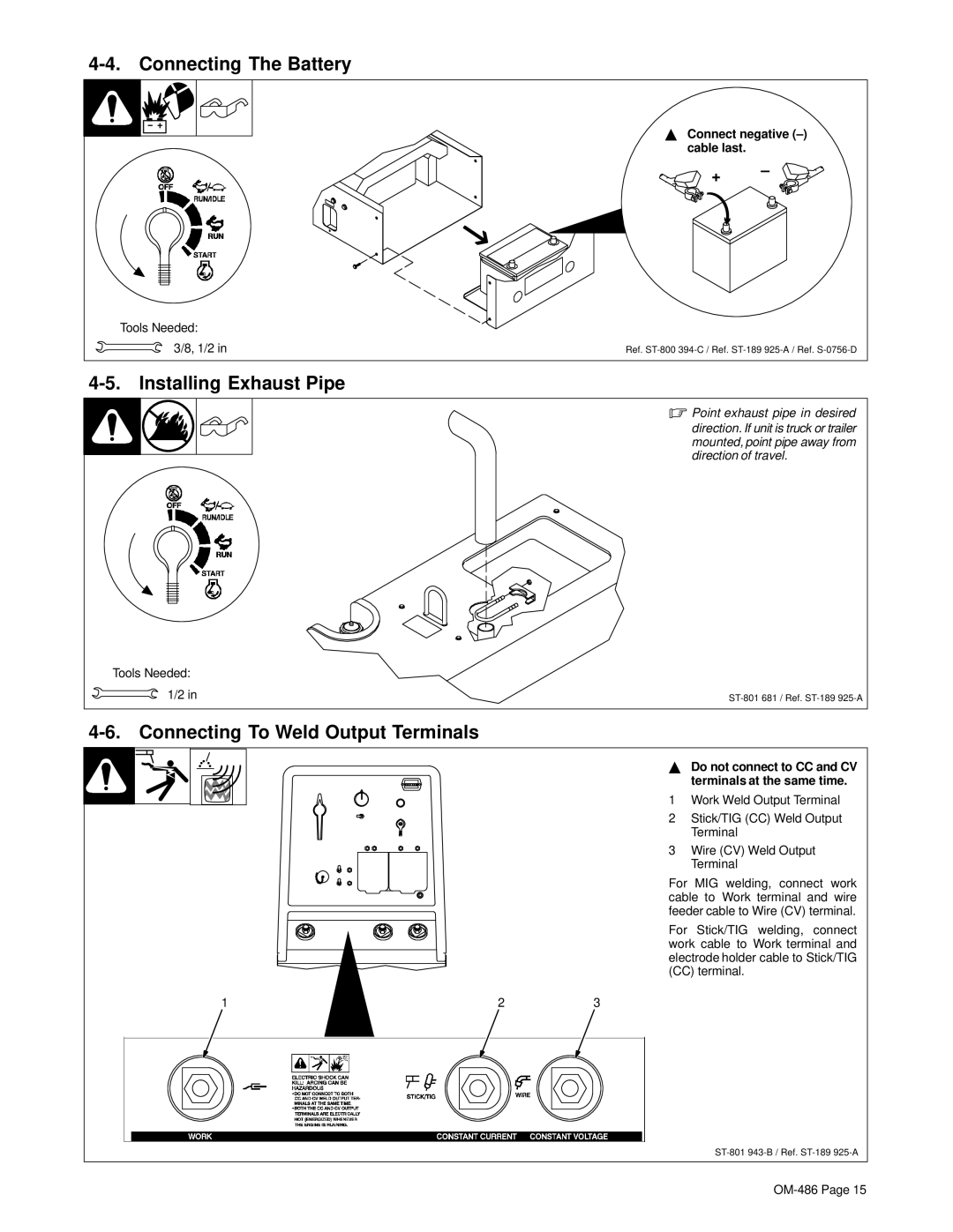
1 Stabilizer
2 Inner Lead 79
3 Middle Lead 79
4 Outer Lead 79
5 Wire (CV) Weld Output
Terminal
Middle lead 79 is connected to Wire (CV) weld terminal at the factory. Disconnect middle lead 79 from terminal.
To wet out weld puddle:
Remove insulation sleeve from in- ner lead 79. Connect inner lead 79 to Wire (CV) terminal, reusing hardware.
To stiffen weld puddle:
Remove insulation sleeve from out- er lead 79. Connect outer lead 79 to Wire (CV) terminal, reusing hardware.
Slide sleeves over unused leads 79, and secure with cable ties. Reinstall panels.
1
4 3 2
5
79
Tools Needed:
3/8, 7/16 in