
SECTION 6 – OPERATING AUXILIARY EQUIPMENT
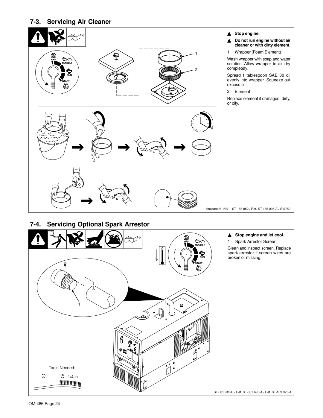
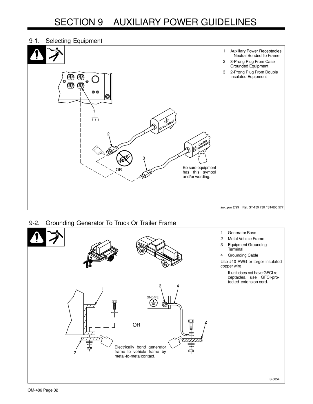
6-1. Auxiliary Power Receptacles And Circuit Breakers
4
1
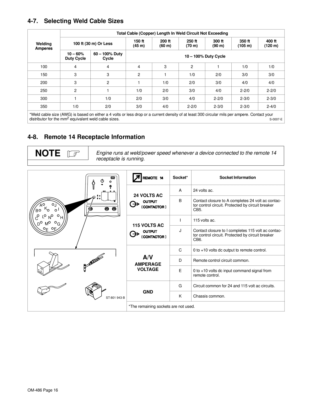
5
23
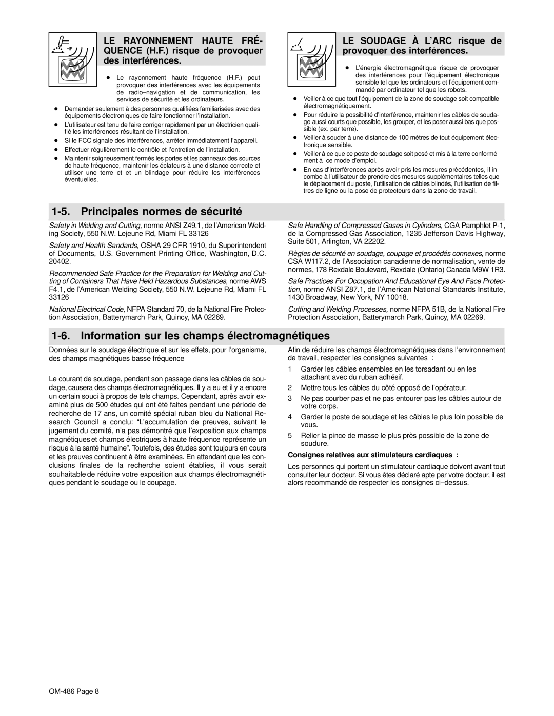
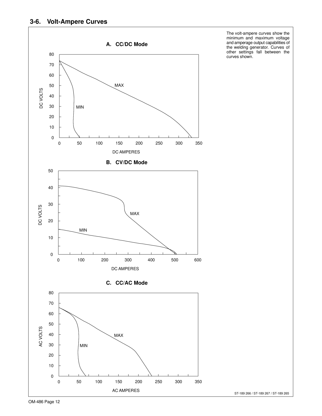
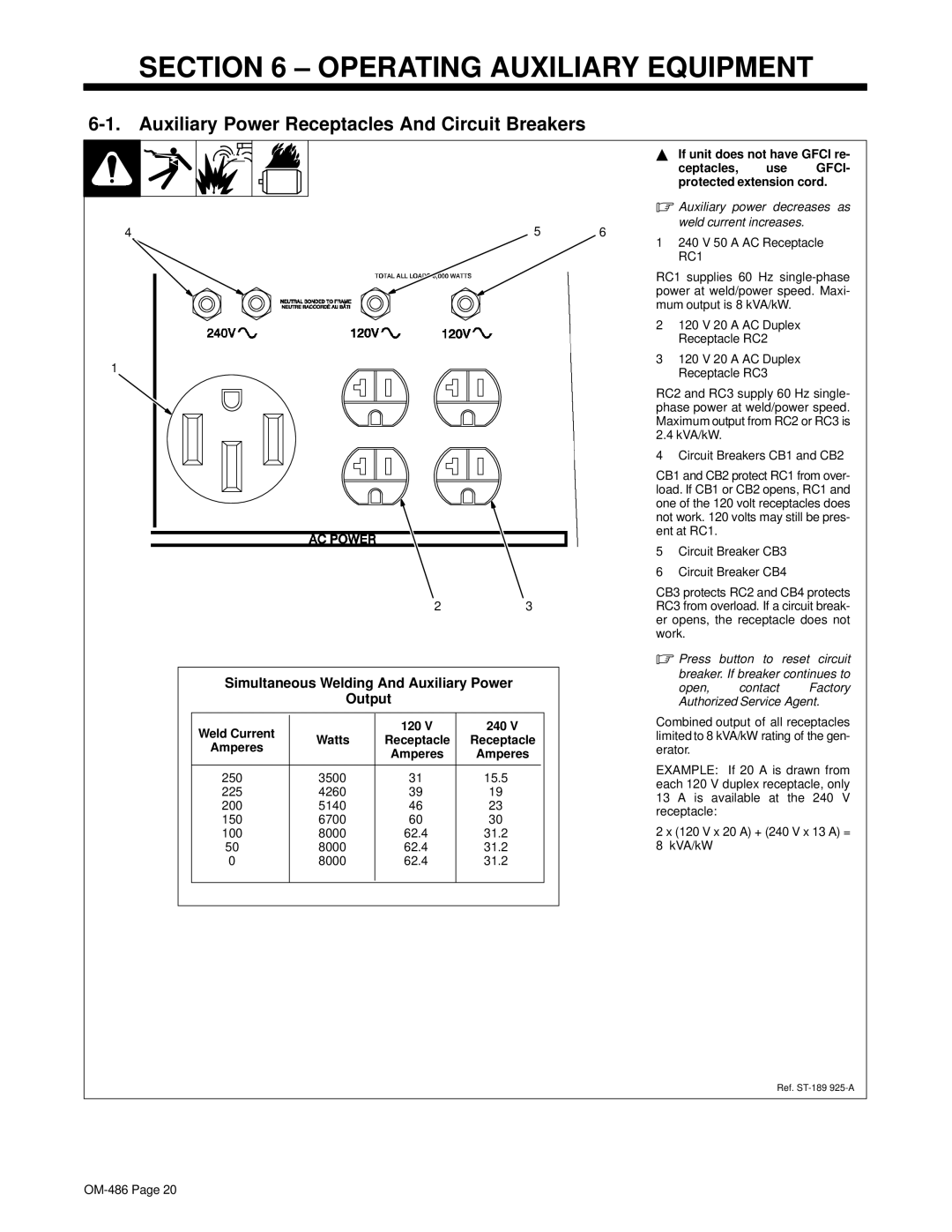
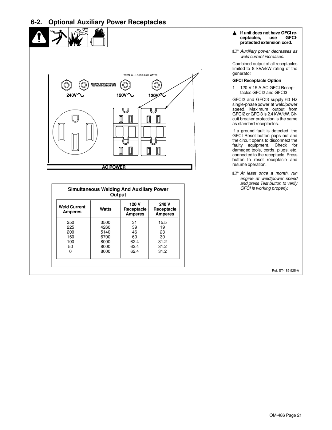
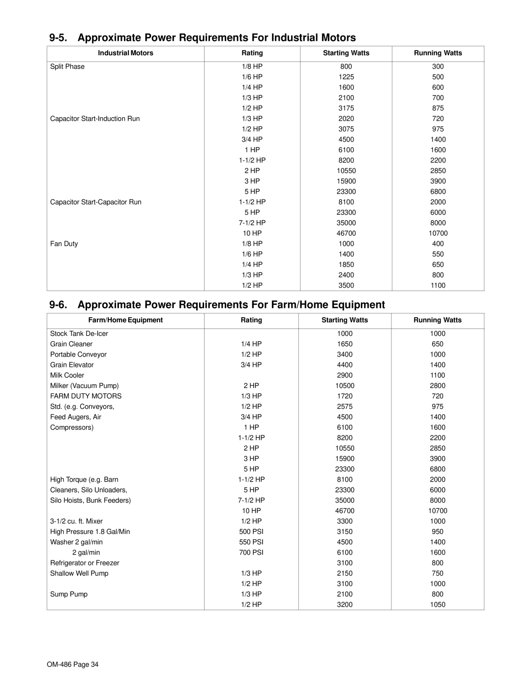
Simultaneous Welding And Auxiliary Power
Output
Weld Current |
| 120 V | 240 V |
|
Watts | Receptacle | Receptacle |
| |
Amperes |
| |||
| Amperes | Amperes |
| |
|
|
| ||
|
|
|
|
|
250 | 3500 | 31 | 15.5 |
|
225 | 4260 | 39 | 19 |
|
200 | 5140 | 46 | 23 |
|
150 | 6700 | 60 | 30 |
|
100 | 8000 | 62.4 | 31.2 |
|
50 | 8000 | 62.4 | 31.2 |
|
0 | 8000 | 62.4 | 31.2 |
|
|
|
|
|
|
YIf unit does not have GFCI re-
ceptacles, use GFCI- protected extension cord.
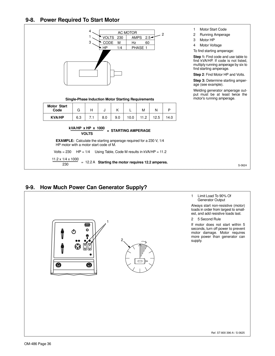
.Auxiliary power decreases as weld current increases.
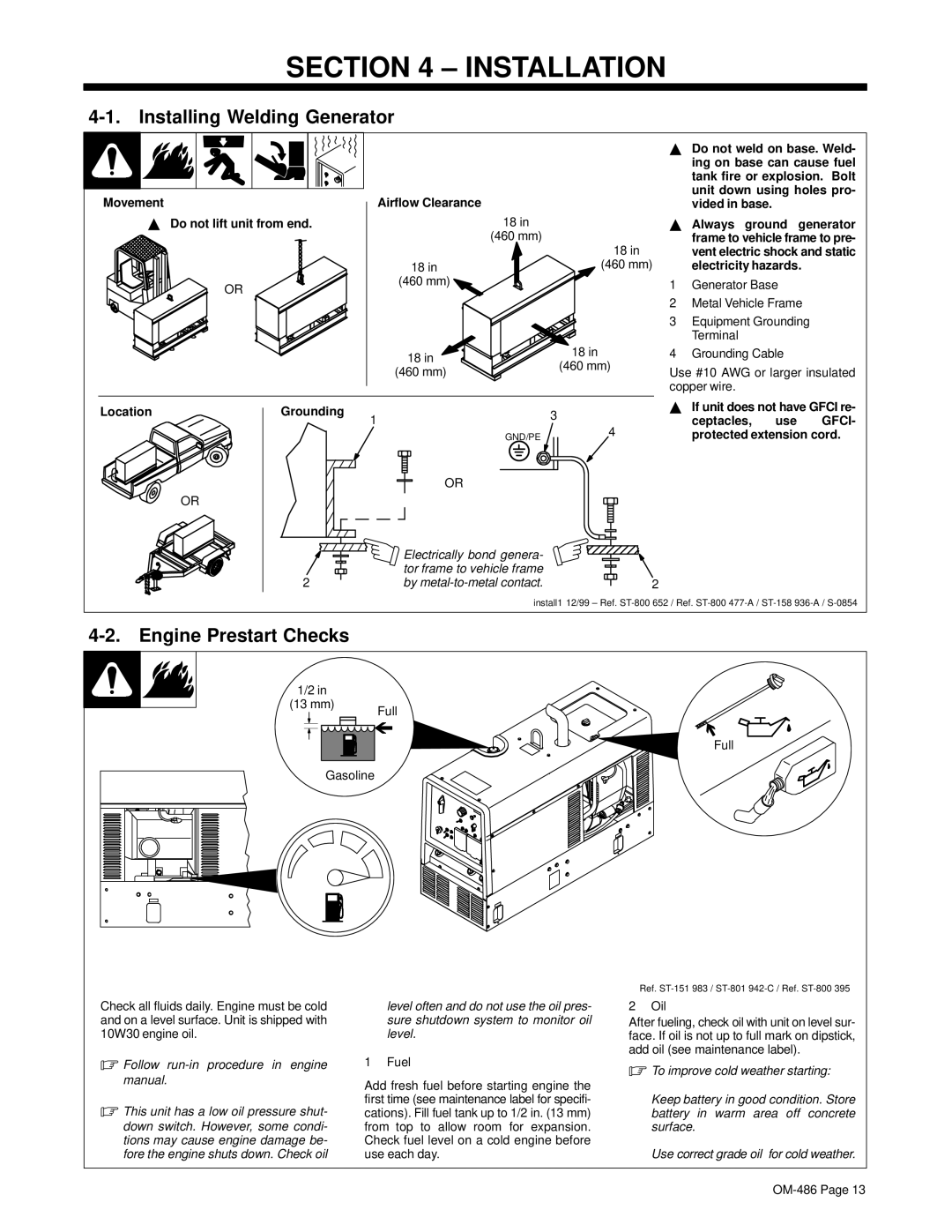
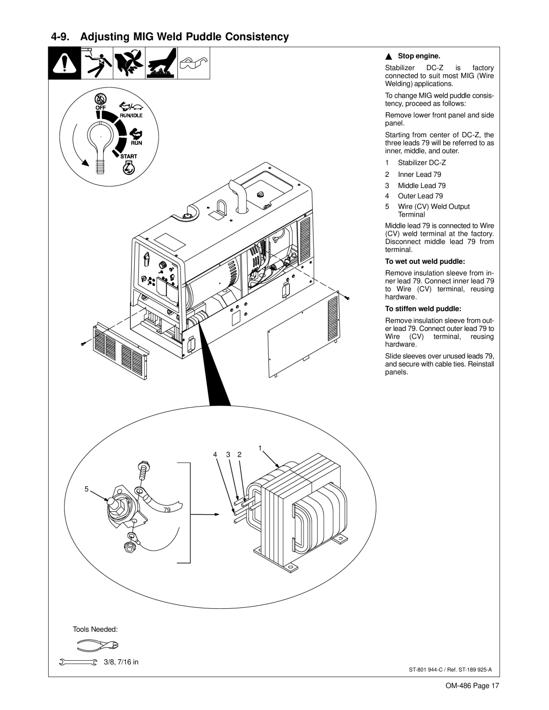
6
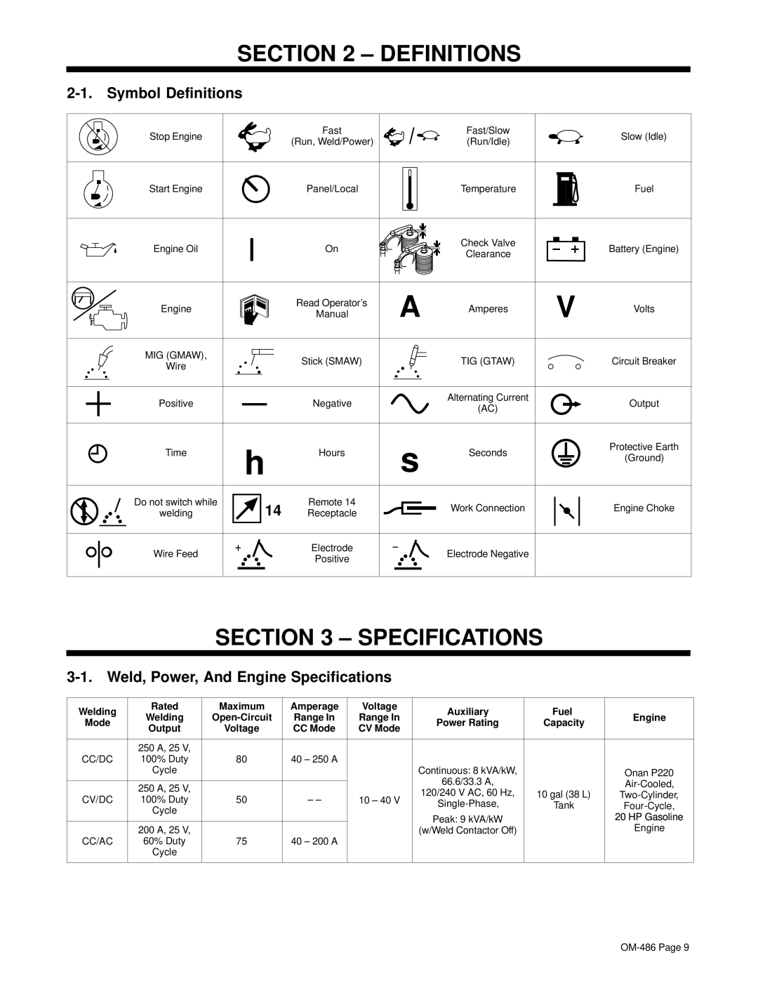
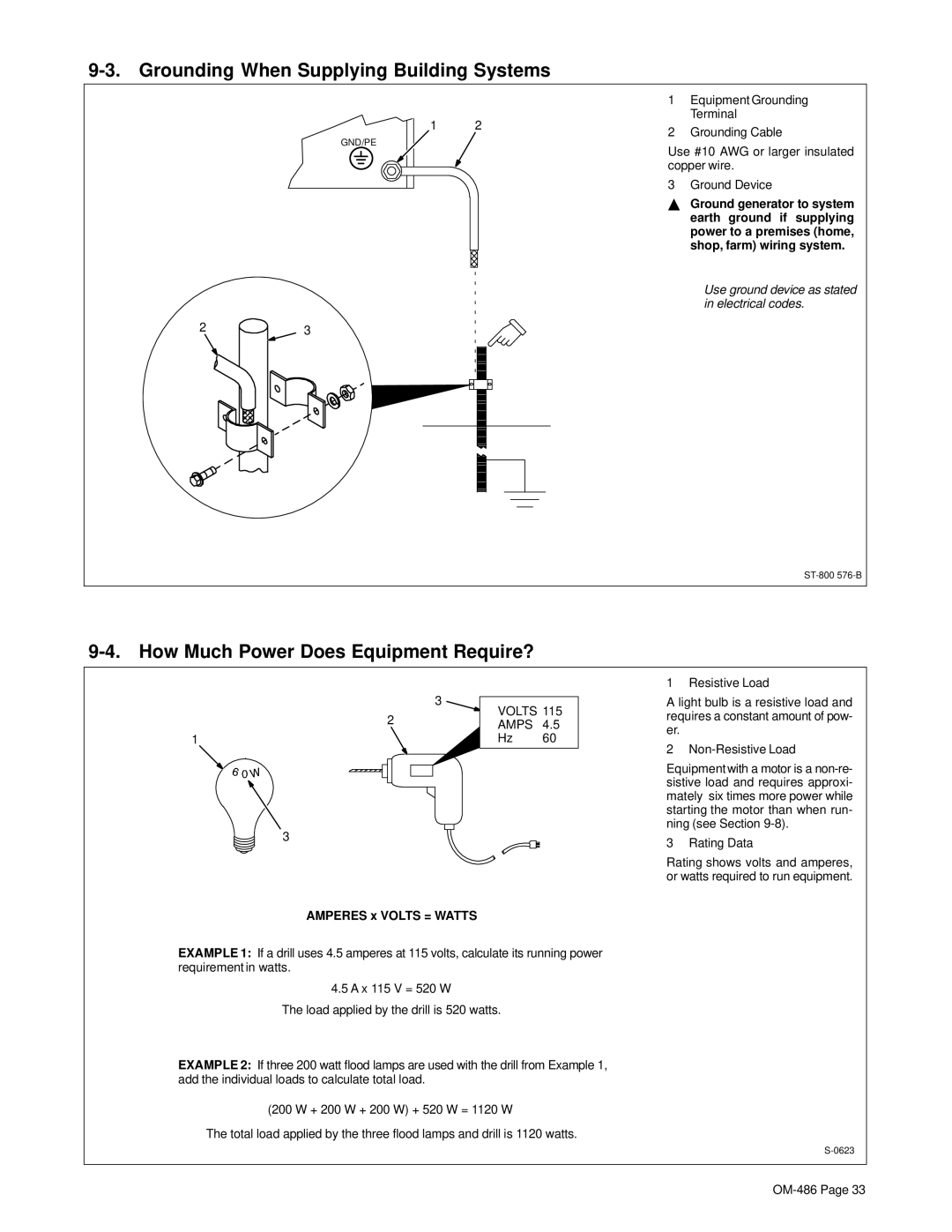
1240 V 50 A AC Receptacle RC1
RC1 supplies 60 Hz
2120 V 20 A AC Duplex Receptacle RC2
3120 V 20 A AC Duplex Receptacle RC3
RC2 and RC3 supply 60 Hz single- phase power at weld/power speed. Maximum output from RC2 or RC3 is 2.4 kVA/kW.
4 Circuit Breakers CB1 and CB2
CB1 and CB2 protect RC1 from over- load. If CB1 or CB2 opens, RC1 and one of the 120 volt receptacles does not work. 120 volts may still be pres- ent at RC1.
5Circuit Breaker CB3
6Circuit Breaker CB4
CB3 protects RC2 and CB4 protects RC3 from overload. If a circuit break- er opens, the receptacle does not work.
.Press button to reset circuit breaker. If breaker continues to
open, contact Factory Authorized Service Agent.
Combined output of all receptacles limited to 8 kVA/kW rating of the gen- erator.
EXAMPLE: If 20 A is drawn from each 120 V duplex receptacle, only 13 A is available at the 240 V receptacle:
2 x (120 V x 20 A) + (240 V x 13 A) = 8 kVA/kW
Ref.