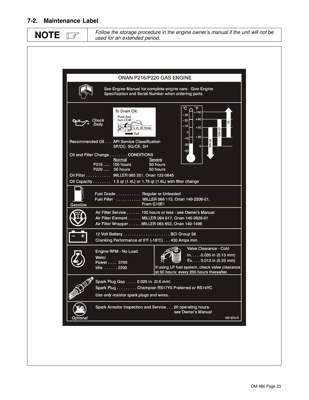
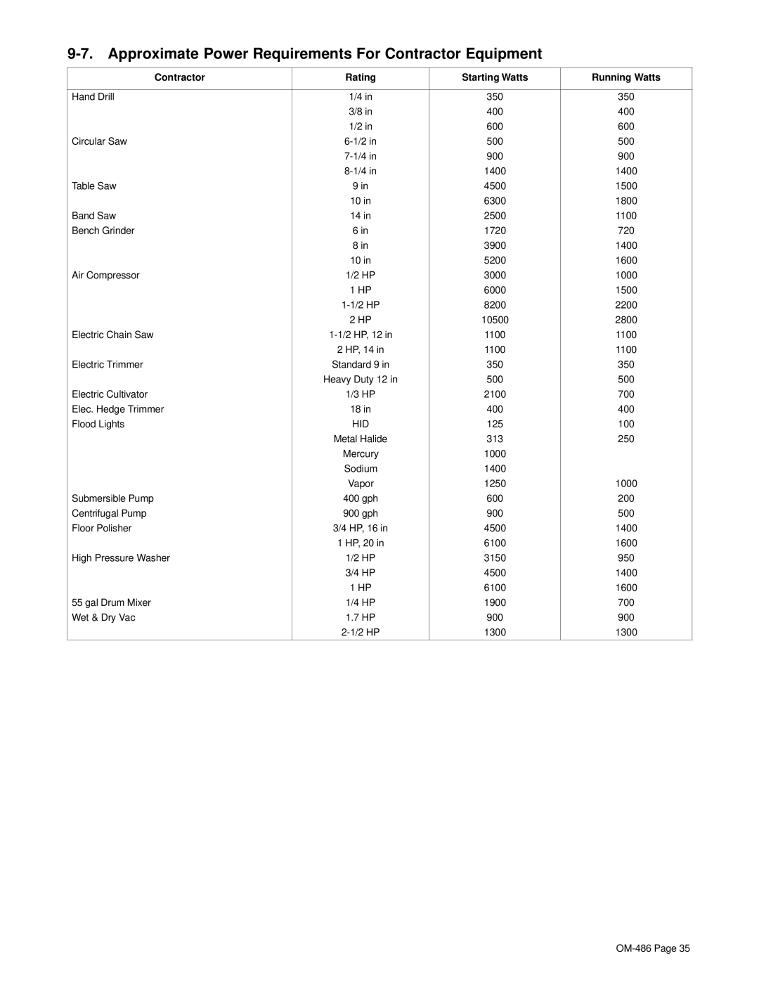
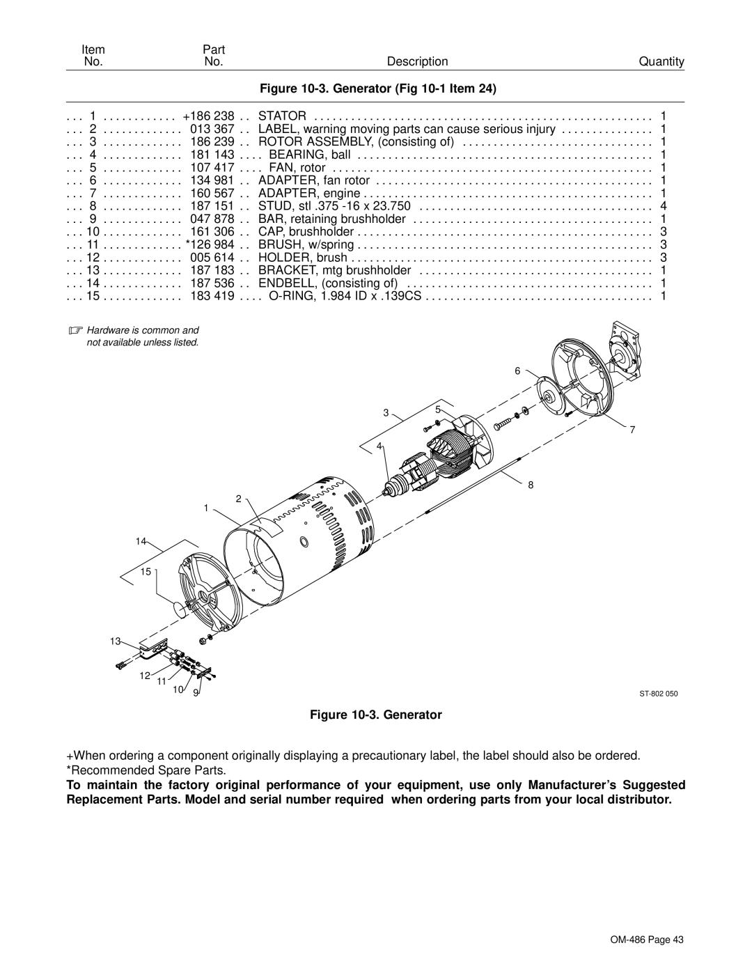


7-7. Overload Protection
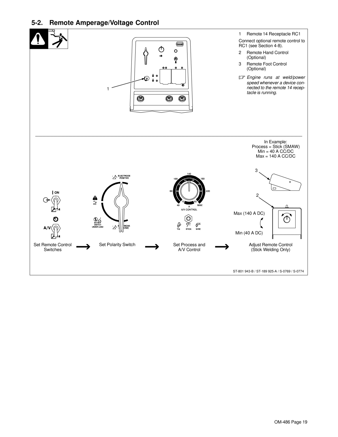
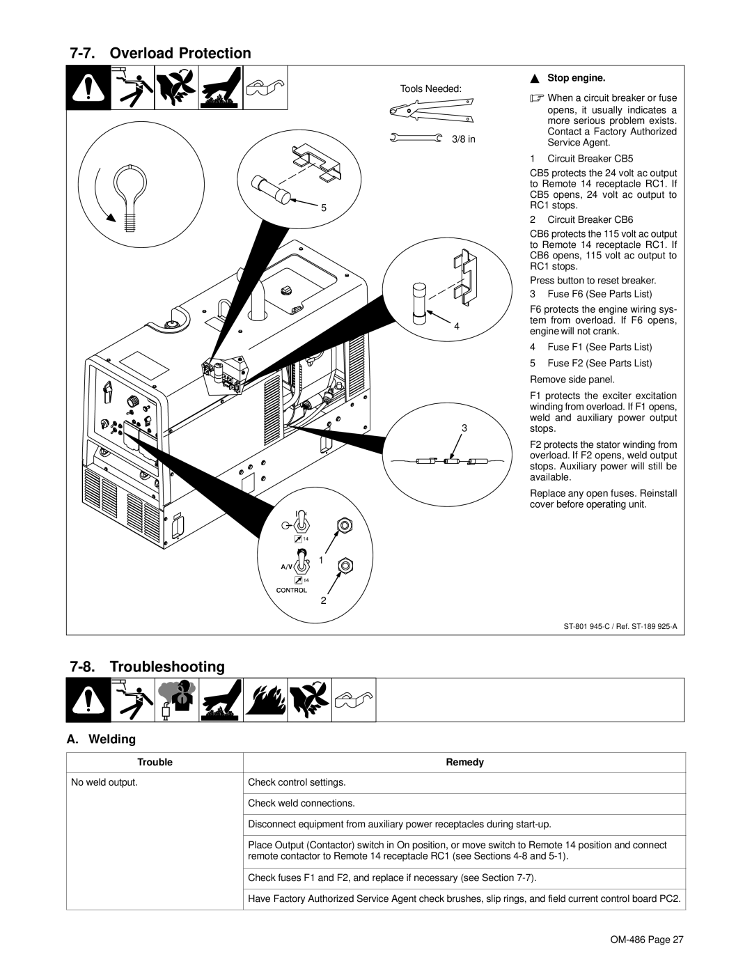
Tools Needed:
3/8 in
5
4
3
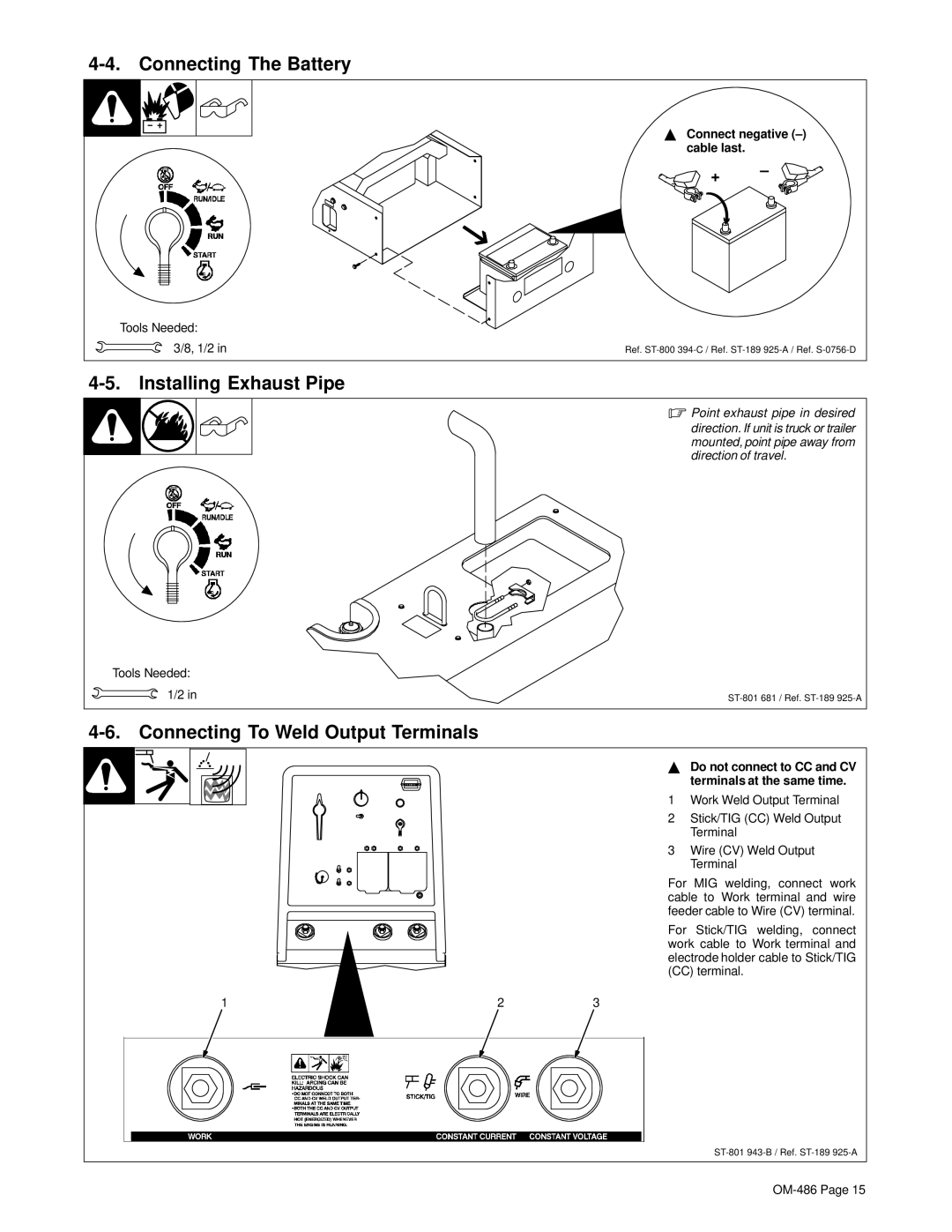
YStop engine.
.When a circuit breaker or fuse opens, it usually indicates a more serious problem exists. Contact a Factory Authorized Service Agent.
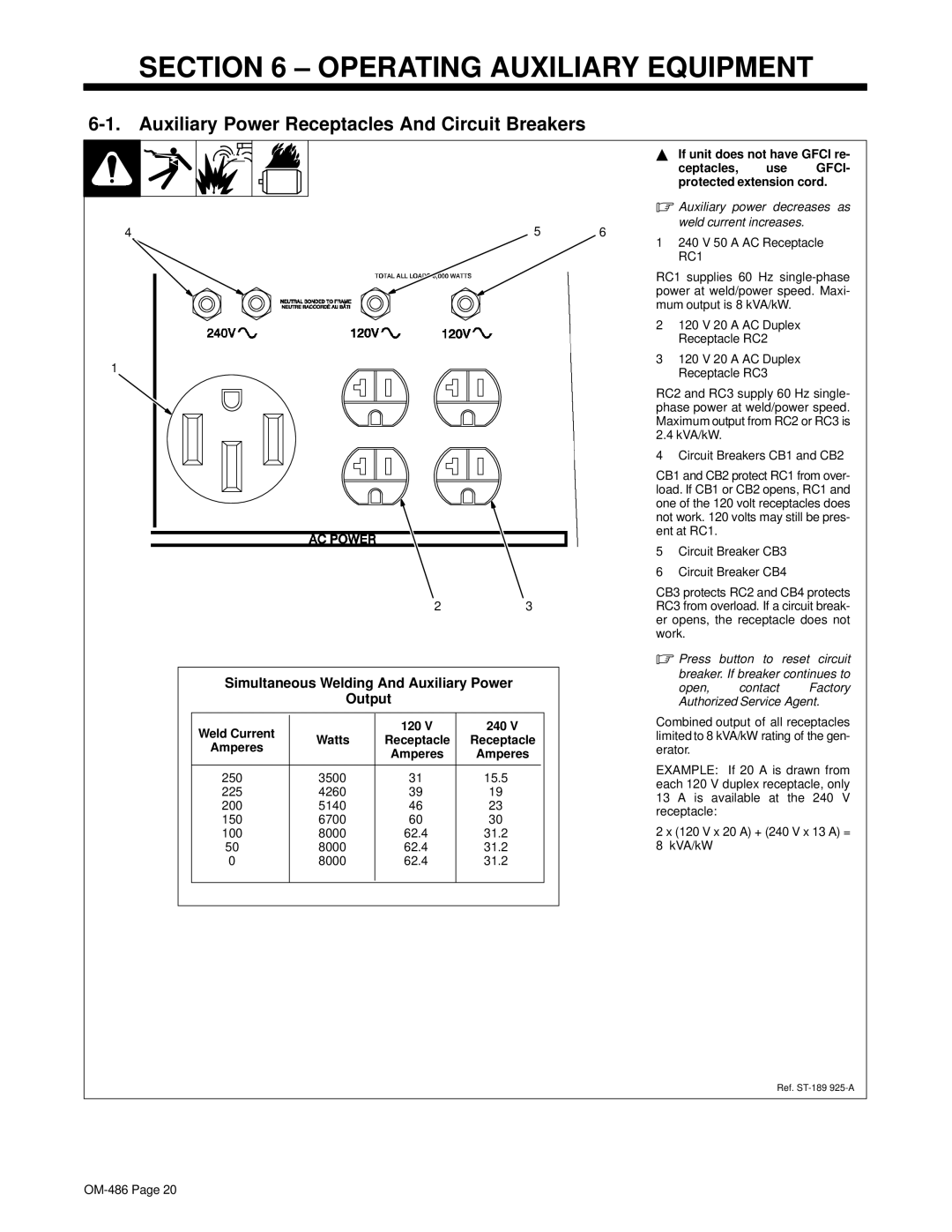
1 Circuit Breaker CB5
CB5 protects the 24 volt ac output to Remote 14 receptacle RC1. If CB5 opens, 24 volt ac output to RC1 stops.
2 Circuit Breaker CB6
CB6 protects the 115 volt ac output to Remote 14 receptacle RC1. If CB6 opens, 115 volt ac output to RC1 stops.
Press button to reset breaker. 3 Fuse F6 (See Parts List)
F6 protects the engine wiring sys- tem from overload. If F6 opens, engine will not crank.
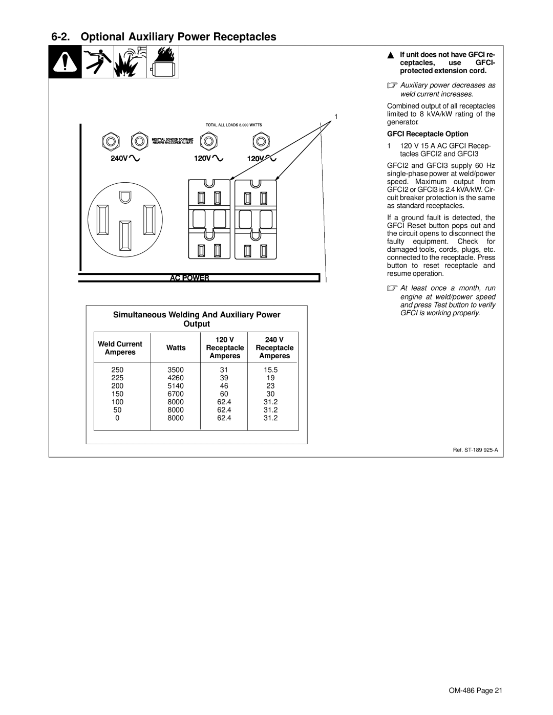
4Fuse F1 (See Parts List)
5Fuse F2 (See Parts List)
Remove side panel.
F1 protects the exciter excitation winding from overload. If F1 opens, weld and auxiliary power output stops.
F2 protects the stator winding from overload. If F2 opens, weld output stops. Auxiliary power will still be available.
Replace any open fuses. Reinstall cover before operating unit.
1
2
7-8. Troubleshooting
A. Welding
Trouble | Remedy |
|
|
No weld output. | Check control settings. |
|
|
| Check weld connections. |
|
|
| Disconnect equipment from auxiliary power receptacles during |
|
|
| Place Output (Contactor) switch in On position, or move switch to Remote 14 position and connect |
| remote contactor to Remote 14 receptacle RC1 (see Sections |
|
|
| Check fuses F1 and F2, and replace if necessary (see Section |
|
|
| Have Factory Authorized Service Agent check brushes, slip rings, and field current control board PC2. |
|
|