


8
7 |
9
11
18
| 6 |
|
| 5 |
|
| 4 |
|
| 3 |
|
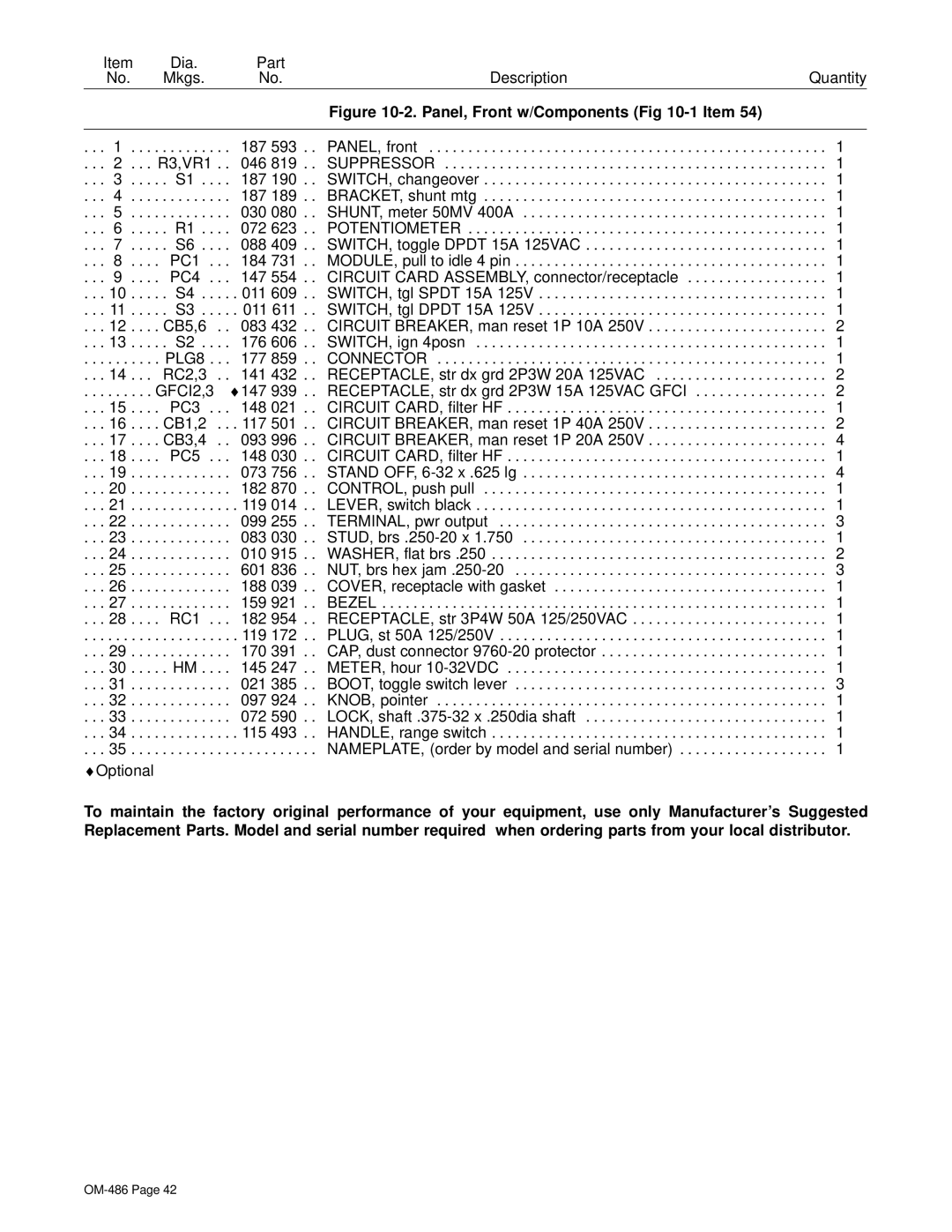
Figure 10- | 2 |
|
1 |
| |
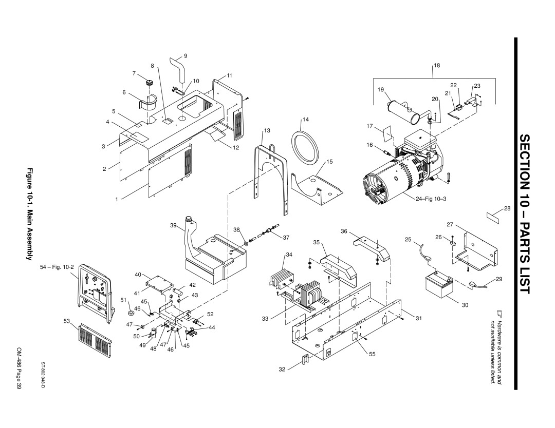
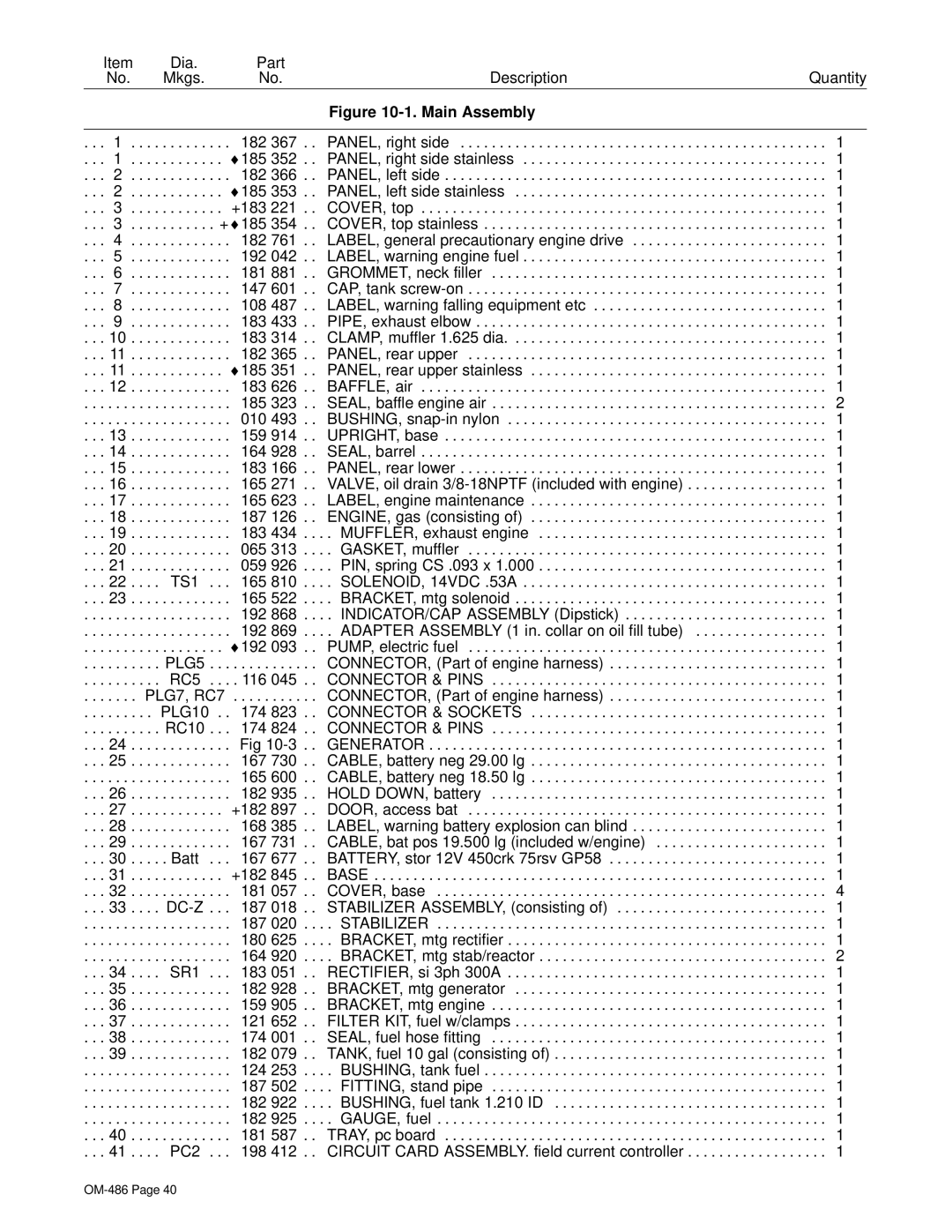
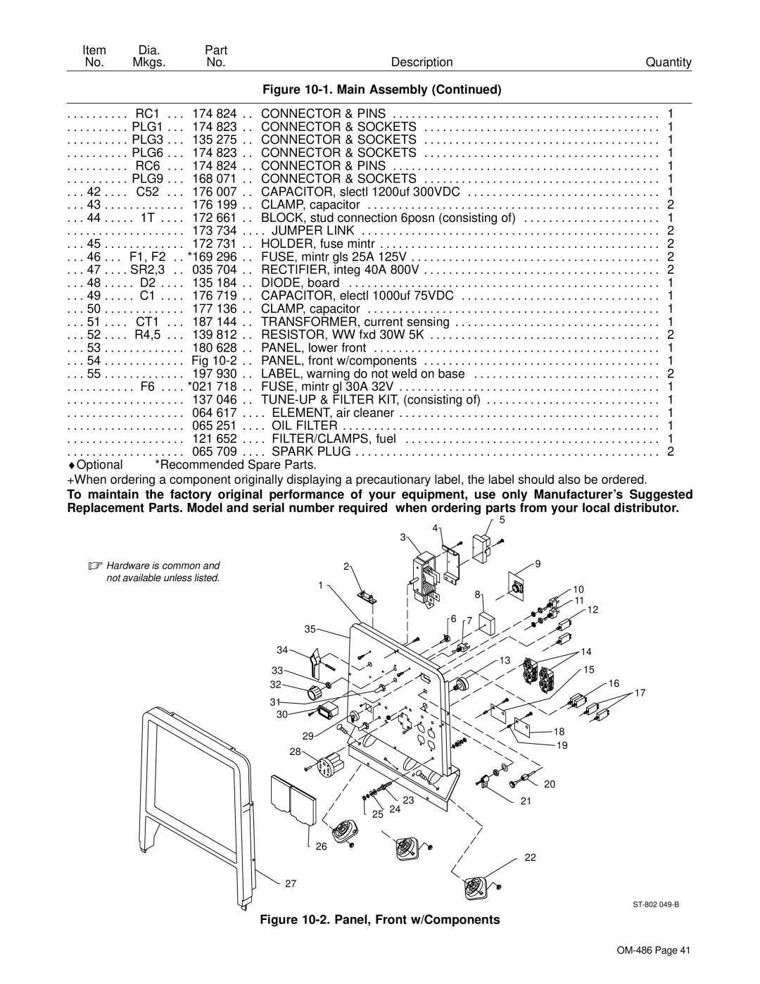
1. Main Assembly |
|
|
| 54 – Fig. |
|
|
| 40 |
|
| 41 |
| 51 | 45 |
|
| 46 |
39
![]() 10
10
42
43
| 19 |
| 14 |
| 17 |
| 13 |
12 | 16 |
| |
| 15 |
38 | 36 |
37
35
34
2223
21
20
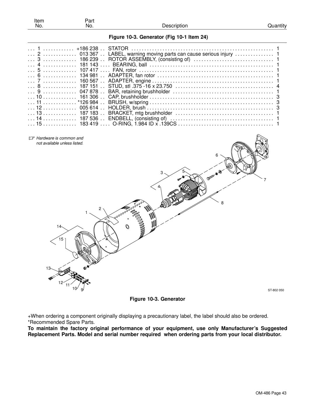
 24–Fig
10–3
![]() 28
28
27 ![]()
2526![]()
![]()
29 |
30 |
SECTION 10 – PARTS LIST
| 53 | 47 |
|
|
|
| |
|
| 50 |
|
| 49 | 48 | |
|
|
47
46
52
33
![]() 44
44
45
55
32 ![]()
31 | . | |
Hardware is | ||
not available | ||
unless listed. | common and |