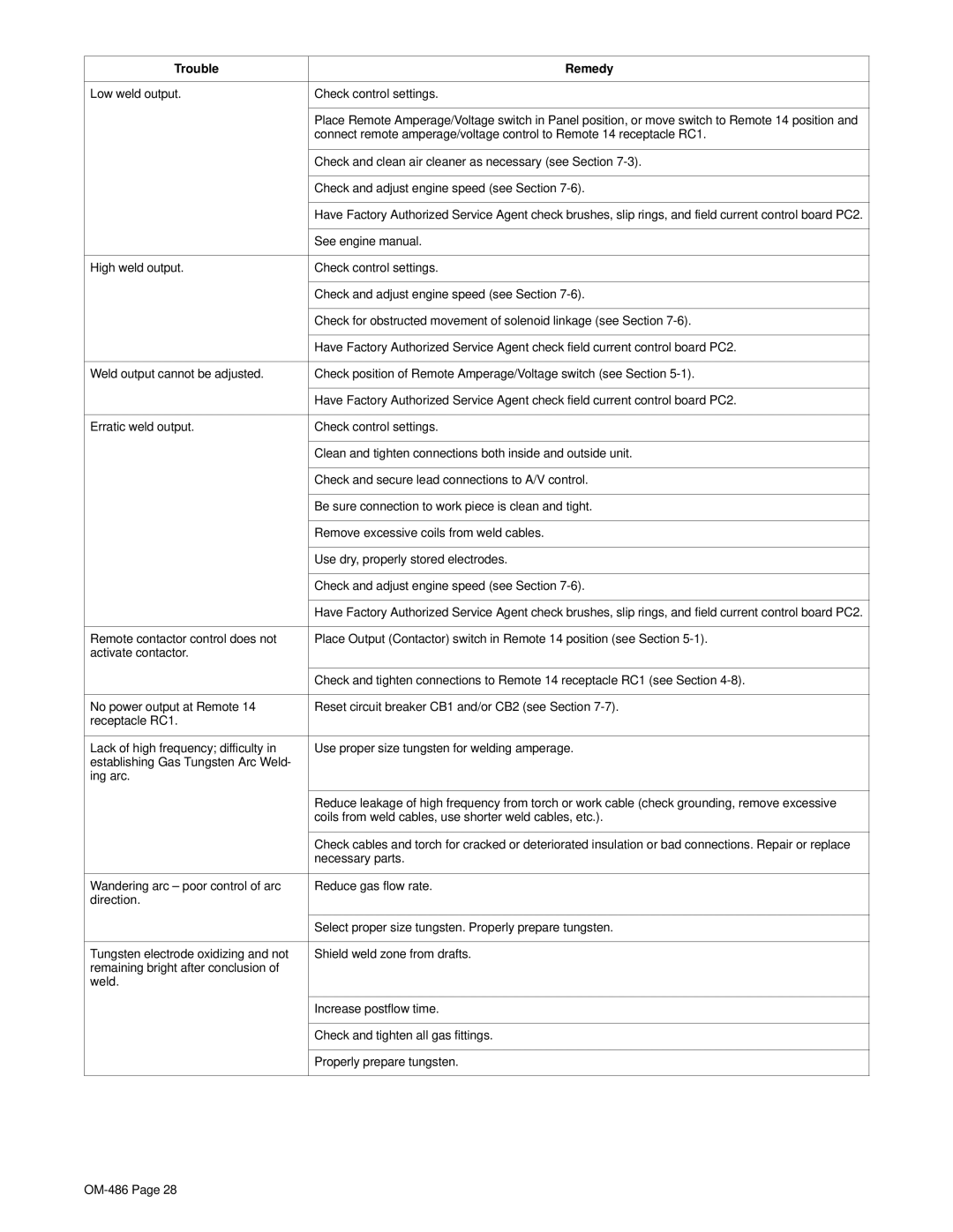


Trouble | Remedy |
|
|
Low weld output. | Check control settings. |
|
|
| Place Remote Amperage/Voltage switch in Panel position, or move switch to Remote 14 position and |
| connect remote amperage/voltage control to Remote 14 receptacle RC1. |
|
|
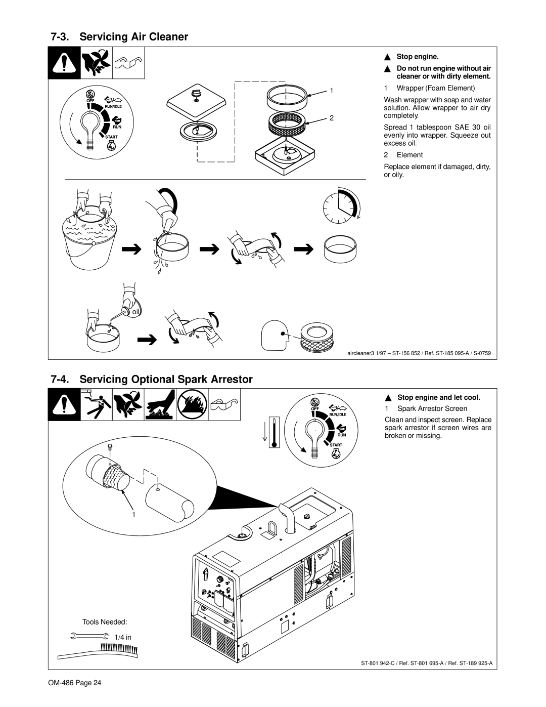
| Check and clean air cleaner as necessary (see Section |
|
|
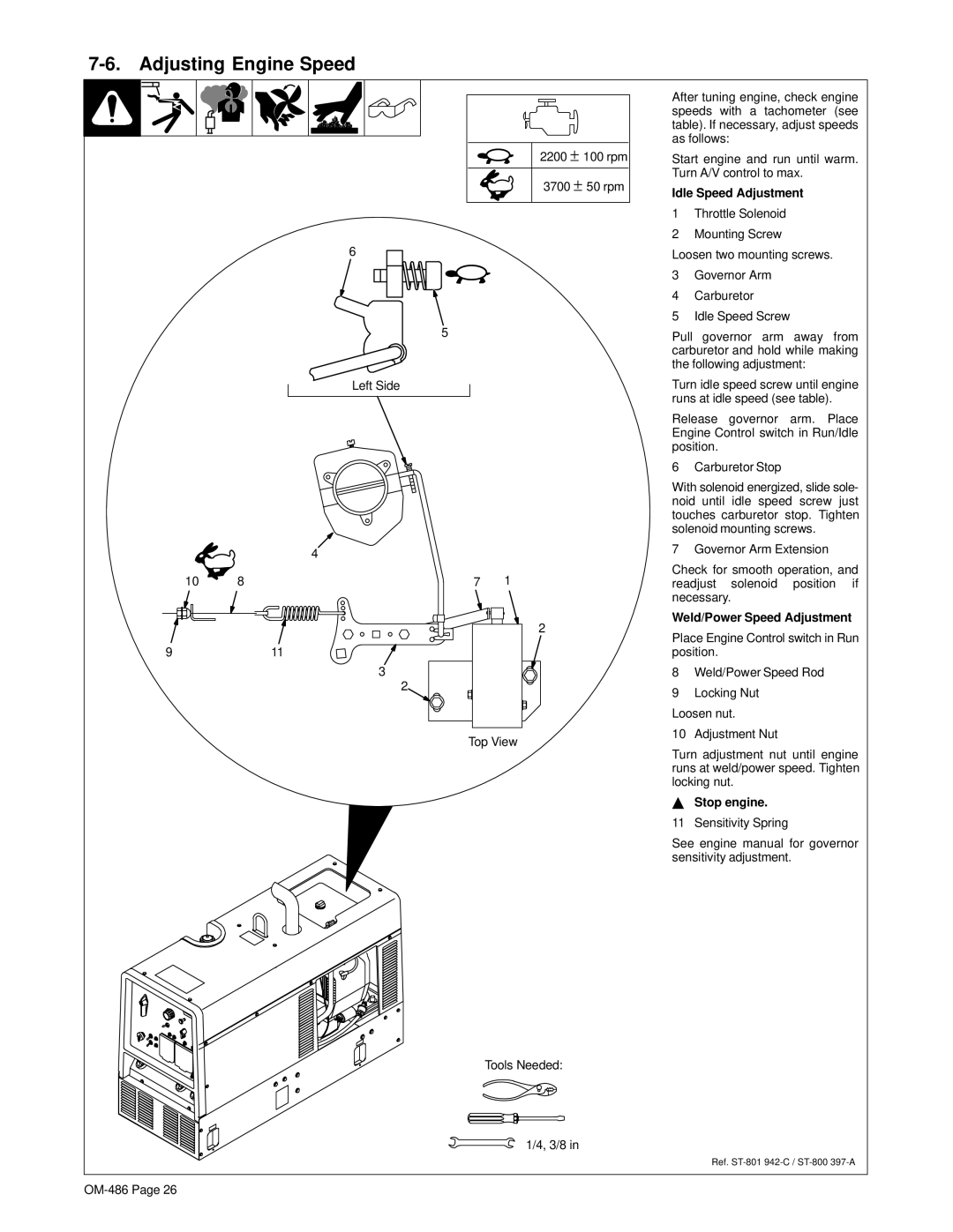
| Check and adjust engine speed (see Section |
|
|
| Have Factory Authorized Service Agent check brushes, slip rings, and field current control board PC2. |
|
|
| See engine manual. |
|
|
High weld output. | Check control settings. |
|
|
| Check and adjust engine speed (see Section |
|
|
| Check for obstructed movement of solenoid linkage (see Section |
|
|
| Have Factory Authorized Service Agent check field current control board PC2. |
|
|
Weld output cannot be adjusted. | Check position of Remote Amperage/Voltage switch (see Section |
|
|
| Have Factory Authorized Service Agent check field current control board PC2. |
|
|
Erratic weld output. | Check control settings. |
|
|
| Clean and tighten connections both inside and outside unit. |
|
|
| Check and secure lead connections to A/V control. |
|
|
| Be sure connection to work piece is clean and tight. |
|
|
| Remove excessive coils from weld cables. |
|
|
| Use dry, properly stored electrodes. |
|
|
| Check and adjust engine speed (see Section |
|
|
| Have Factory Authorized Service Agent check brushes, slip rings, and field current control board PC2. |
|
|
Remote contactor control does not | Place Output (Contactor) switch in Remote 14 position (see Section |
activate contactor. |
|
|
|
| Check and tighten connections to Remote 14 receptacle RC1 (see Section |
|
|
No power output at Remote 14 | Reset circuit breaker CB1 and/or CB2 (see Section |
receptacle RC1. |
|
|
|
Lack of high frequency; difficulty in | Use proper size tungsten for welding amperage. |
establishing Gas Tungsten Arc Weld- |
|
ing arc. |
|
|
|
| Reduce leakage of high frequency from torch or work cable (check grounding, remove excessive |
| coils from weld cables, use shorter weld cables, etc.). |
|
|
| Check cables and torch for cracked or deteriorated insulation or bad connections. Repair or replace |
| necessary parts. |
|
|
Wandering arc – poor control of arc | Reduce gas flow rate. |
direction. |
|
|
|
| Select proper size tungsten. Properly prepare tungsten. |
|
|
Tungsten electrode oxidizing and not | Shield weld zone from drafts. |
remaining bright after conclusion of |
|
weld. |
|
|
|
| Increase postflow time. |
|
|
| Check and tighten all gas fittings. |
|
|
| Properly prepare tungsten. |
|
|