Hobart Welding Products OM-486 manual Auxiliary Power Guidelines, Selecting Equipment

Page 36

SECTION 9 – AUXILIARY POWER GUIDELINES

9-1. Selecting Equipment

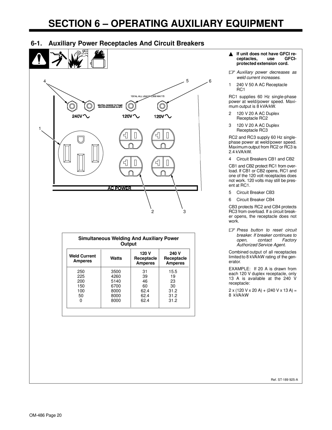
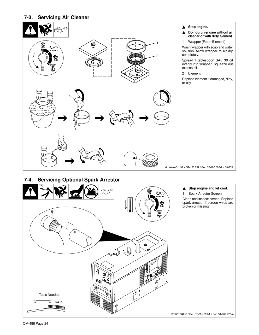
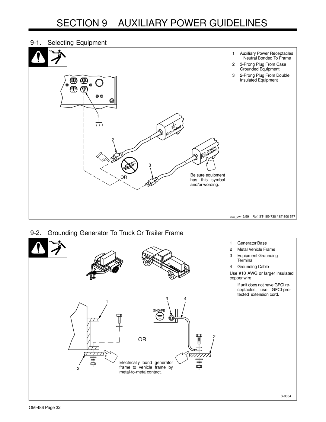
1 Auxiliary Power Receptacles

– Neutral Bonded To Frame

2 3-Prong Plug From Case

Grounded Equipment

3 2-Prong Plug From Double

Insulated Equipment

1

2


3

OR

Be sure equipment

has this symbol


and/or wording.

aux_pwr 2/99 – Ref. ST-159 730 / ST-800 577

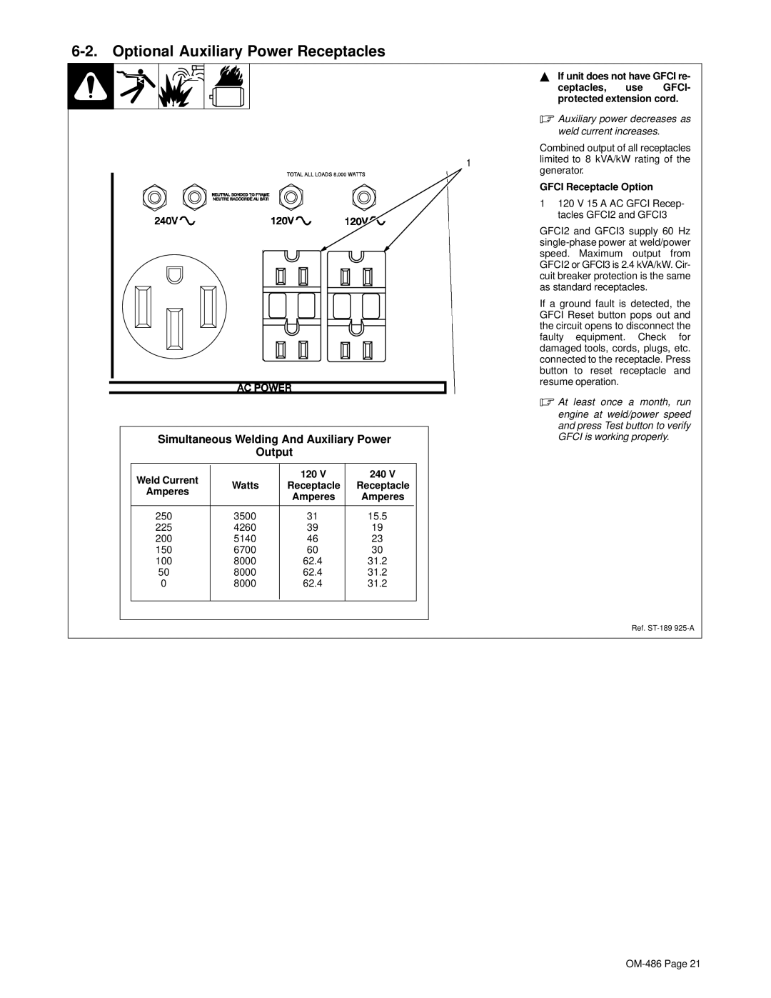
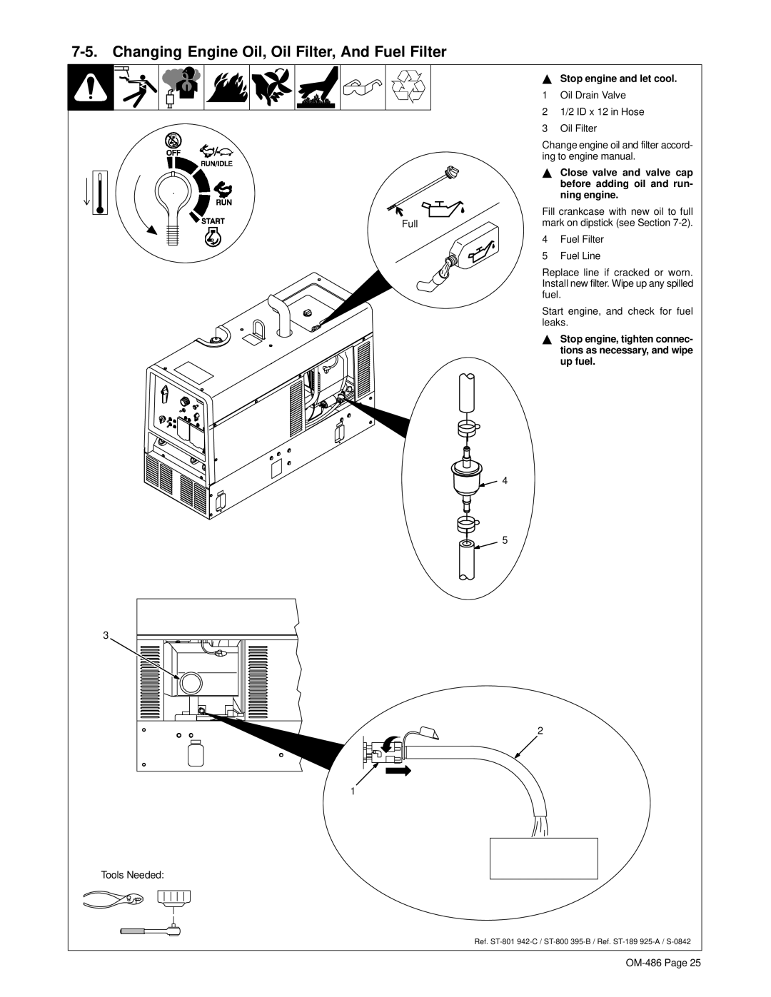
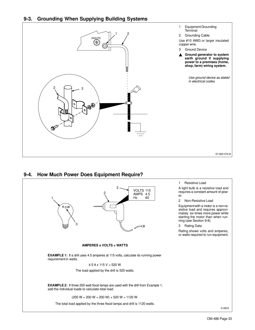
9-2. Grounding Generator To Truck Or Trailer Frame

3 4

1

GND/PE

1Generator Base

2Metal Vehicle Frame

3Equipment Grounding Terminal

4Grounding Cable

Use #10 AWG or larger insulated copper wire.

YIf unit does not have GFCI re- ceptacles, use GFCI-pro- tected extension cord.

OR

2

Electrically bond generator

2frame to vehicle frame by metal-to-metal contact.

S-0854

OM-486 Page 32

Image 36
Contents OM-486 ProcessesDescription From Hobart to You Table of Contents Page Symbol Usage Arc Welding HazardsElectric Shock can kill ARC Rays can burn eyes and skinEngine Hazards Battery Explosion can Blind Moving Parts can cause injuryEngine Exhaust Gases can kill Engine Heat can cause firePrincipal Safety Standards EMF InformationRadiation can cause interference ARC Welding can cause interferenceSignification des symboles Consignes DE SÉ Curité Lire Avant UtilisationUN Choc É Lectrique peut tuer LES Fumé ES ET LES GAZ peuvent ê tre dangereuxLE Soudage peut provoquer un in- cendie ou une explosion DES Particules Volantes peuvent blesser les yeuxDES PIÈ CES Chaudes peuvent provoquer des brû lures graves LE Bruit peut affecter l’ouïeDES Organes Mobiles peuvent provoquer des blessures ’EXPLOSION DE LA Batterie peutLA Chaleur DU Moteur peut pro- voquer un incendie LA Chute DE L’APPAREIL peut blesserPrincipales normes de sé curité Information sur les champs é lectromagné tiquesLE Soudage À L’ARC risque de provoquer des interfé rences Consignes relatives aux stimulateurs cardiaquesSpecifications Symbol DefinitionsWeld, Power, And Engine Specifications DefinitionsDimensions, Weights, and Operating Angles DimensionsFuel Consumption Auxiliary Power Curve Exceeding duty cycle can damage unit and void warrantyDuty Cycle CC/DC Mode CV/DC ModeCC/AC Mode Volt-Ampere CurvesInstallation Installing Welding GeneratorEngine Prestart Checks Activating The Dry Charge Battery If Applicable Do not overfill battery cellsRead and follow all instruc ChargerConnecting The Battery Installing Exhaust PipeConnecting To Weld Output Terminals Connect negative cable lastSelecting Weld Cable Sizes Remote 14 Receptacle Information100 ft 30 m Or Less 10 100% Duty CycleAdjusting MIG Weld Puddle Consistency Stop engineTo wet out weld puddle To stiffen weld puddleDC Polarity/AC Switch Do not switch under loadRemote Amperage/Voltage Switch Operating Welding GeneratorRemote Amperage/Voltage Control Auxiliary Power Receptacles And Circuit Breakers Operating Auxiliary EquipmentWeld Current 120 240 Optional Auxiliary Power Receptacles Gfci Receptacle OptionMaintenance and Troubleshooting Maintenance Label Servicing Air Cleaner Servicing Optional Spark ArrestorStop engine and let cool Changing Engine Oil, Oil Filter, And Fuel Filter Adjusting Engine Speed Idle Speed AdjustmentWeld/Power Speed Adjustment Troubleshooting Overload ProtectionWelding Trouble RemedyLow weld output Check control settings Check and clean air cleaner as necessary see SectionCheck and adjust engine speed see Section See engine manual Auxiliary Power Check receptacle wiring and connections Engine Check governor according to engine manualElectrical Diagram Circuit Diagram For Welding GeneratorST-190 578-B Auxiliary Power Guidelines Selecting EquipmentGrounding Generator To Truck Or Trailer Frame Grounding When Supplying Building Systems How Much Power Does Equipment Require?Earth ground if supplying Amperes x Volts = WattsApproximate Power Requirements For Industrial Motors Approximate Power Requirements For Farm/Home EquipmentIndustrial Motors Rating Starting Watts Running Watts Farm/Home Equipment Rating Starting Watts Running WattsApproximate Power Requirements For Contractor Equipment Contractor Rating Starting Watts Running WattsPower Required To Start Motor How Much Power Can Generator Supply?Single-Phase Induction Motor Starting Requirements KVA/HP x HP xTypical Connections To Supply Standby Power 240 120 GroundSelecting Extension Cord Use Shortest Cord Possible Current Load Watts AmperesParts List Main Assembly24-Fig Dia Part Description Mkgs Quantity Panel, Front w/Components Panel, Front w/Components -1 Item Generator -1 Item Page Page Page Service SupportContact your Distributor for Hobart Welding ProductsCall