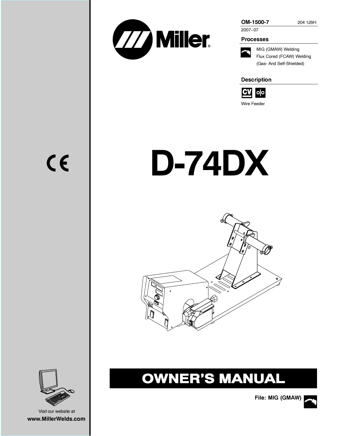
Miller Electric D-74DX manual Directives, Standards, Decwire6/05

Page 4

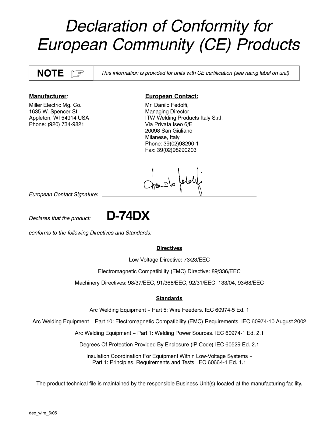
Declaration of Conformity for

European Community (CE) Products

NOTE

This information is provided for units with CE certification (see rating label on unit).

Manufacturer:

European Contact:

Miller Electric Mg. Co.

Mr. Danilo Fedolfi,

1635 W. Spencer St.

Managing Director

Appleton, WI 54914 USA

ITW Welding Products Italy S.r.l.

Phone: (920) 734-9821

Via Privata Iseo 6/E


20098 San Giuliano


Milanese, Italy


Phone: 39(02)98290-1


Fax: 39(02)98290203

European Contact Signature:


Declares that the product:

D-74DX

conforms to the following Directives and Standards:

Directives

Low Voltage Directive: 73/23/EEC

Electromagnetic Compatibility (EMC) Directive: 89/336/EEC

Machinery Directives: 98/37/EEC, 91/368/EEC, 92/31/EEC, 133/04, 93/68/EEC

Standards

Arc Welding Equipment − Part 5: Wire Feeders. IEC 60974-5 Ed. 1

Arc Welding Equipment − Part 10: Electromagnetic Compatibility (EMC) Requirements. IEC 60974-10 August 2002

Arc Welding Equipment − Part 1: Welding Power Sources. IEC 60974-1 Ed. 2.1

Degrees Of Protection Provided By Enclosure (IP Code) IEC 60529 Ed. 2.1

Insulation Coordination For Equipment Within Low-Voltage Systems −

Part 1: Principles, Requirements and Tests: IEC 60664-1 Ed. 1.1

The product technical file is maintained by the responsible Business Unit(s) located at the manufacturing facility.
dec_wire_6/05

Image 4
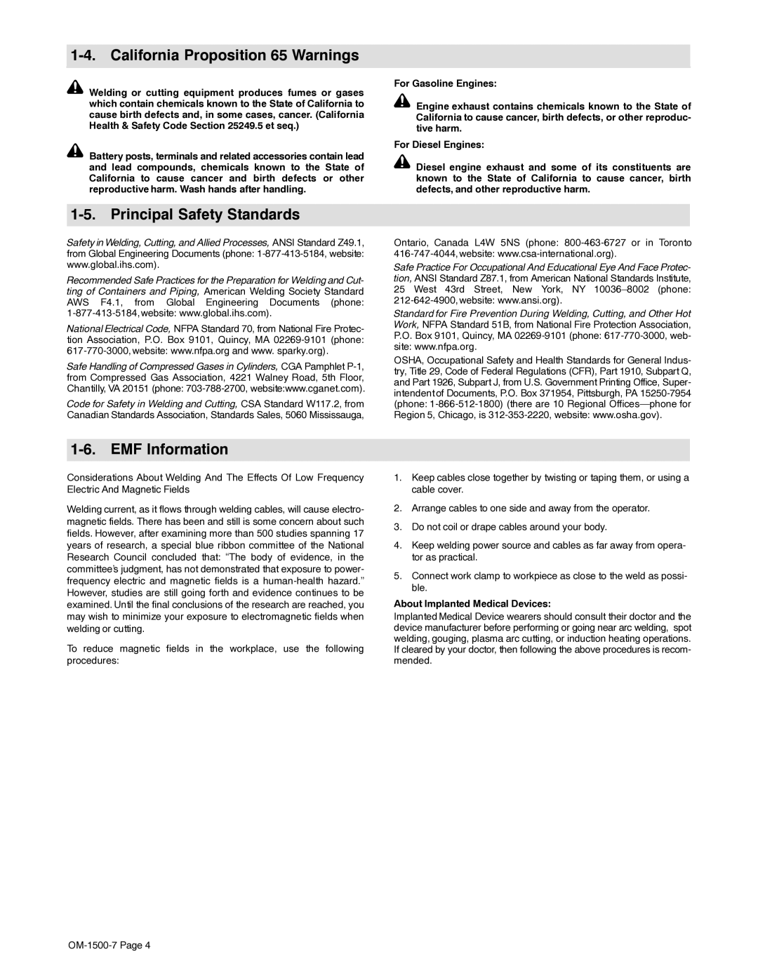
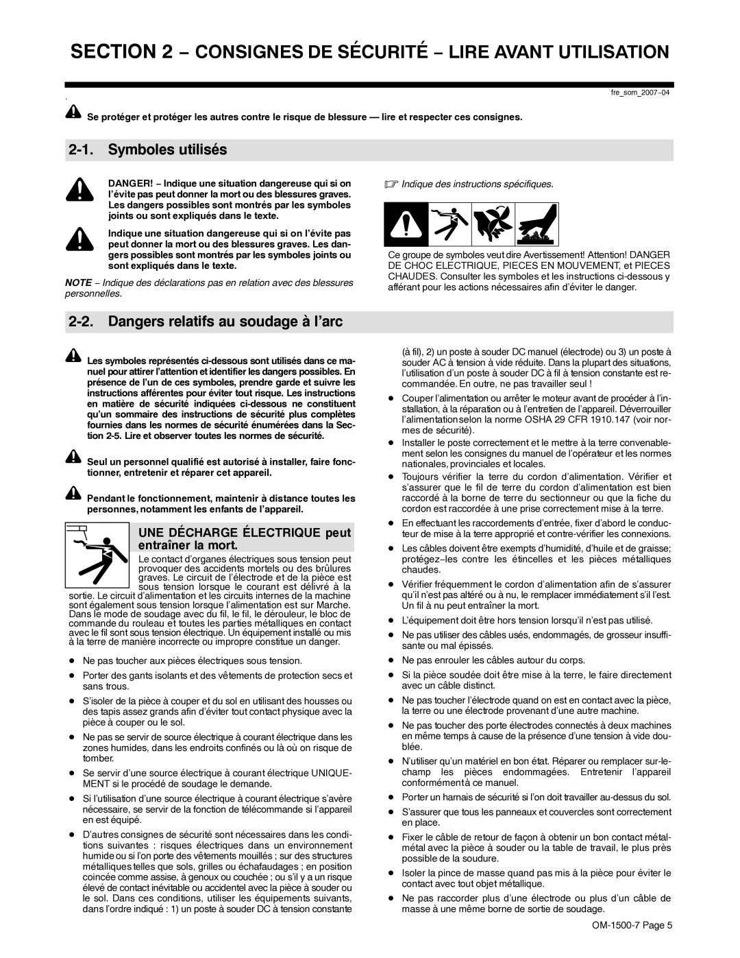
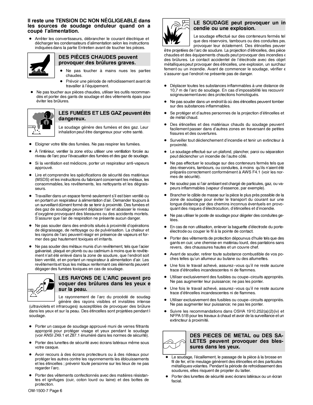
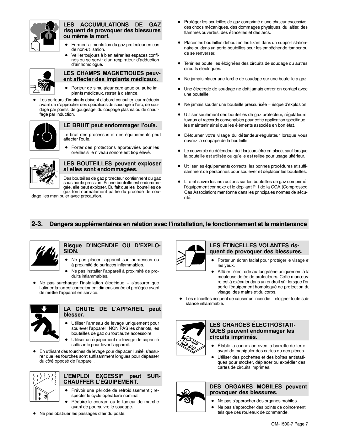
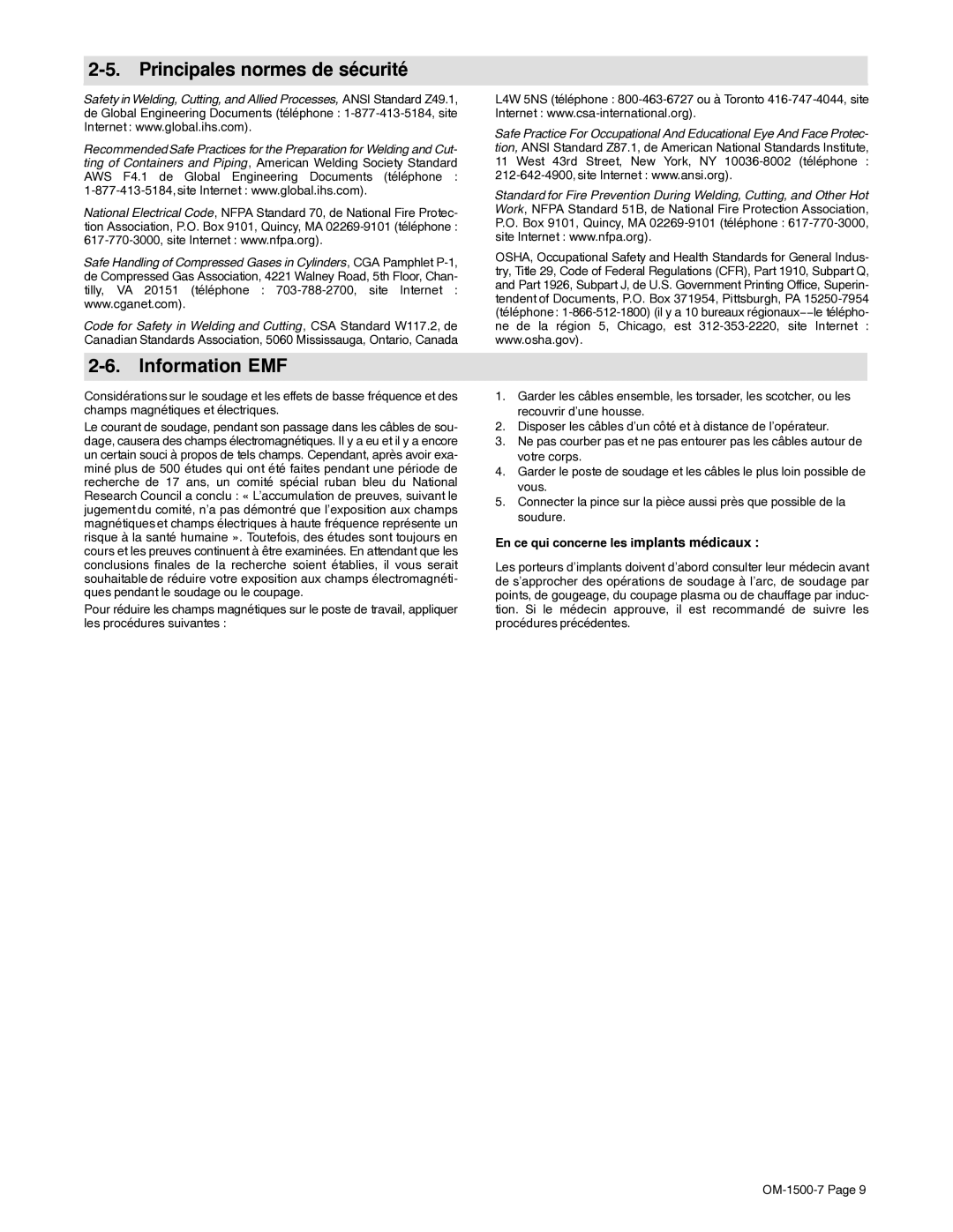
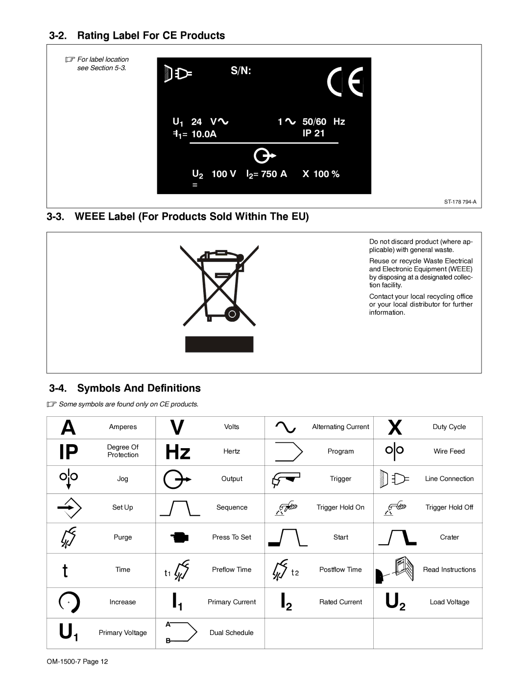
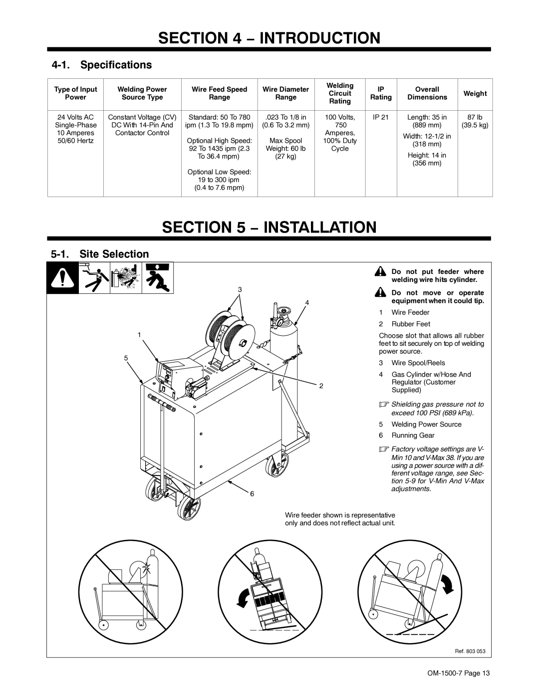
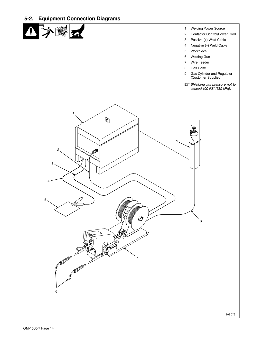
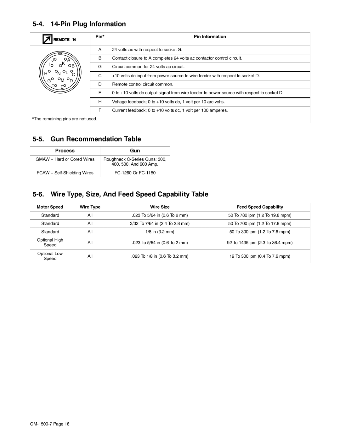
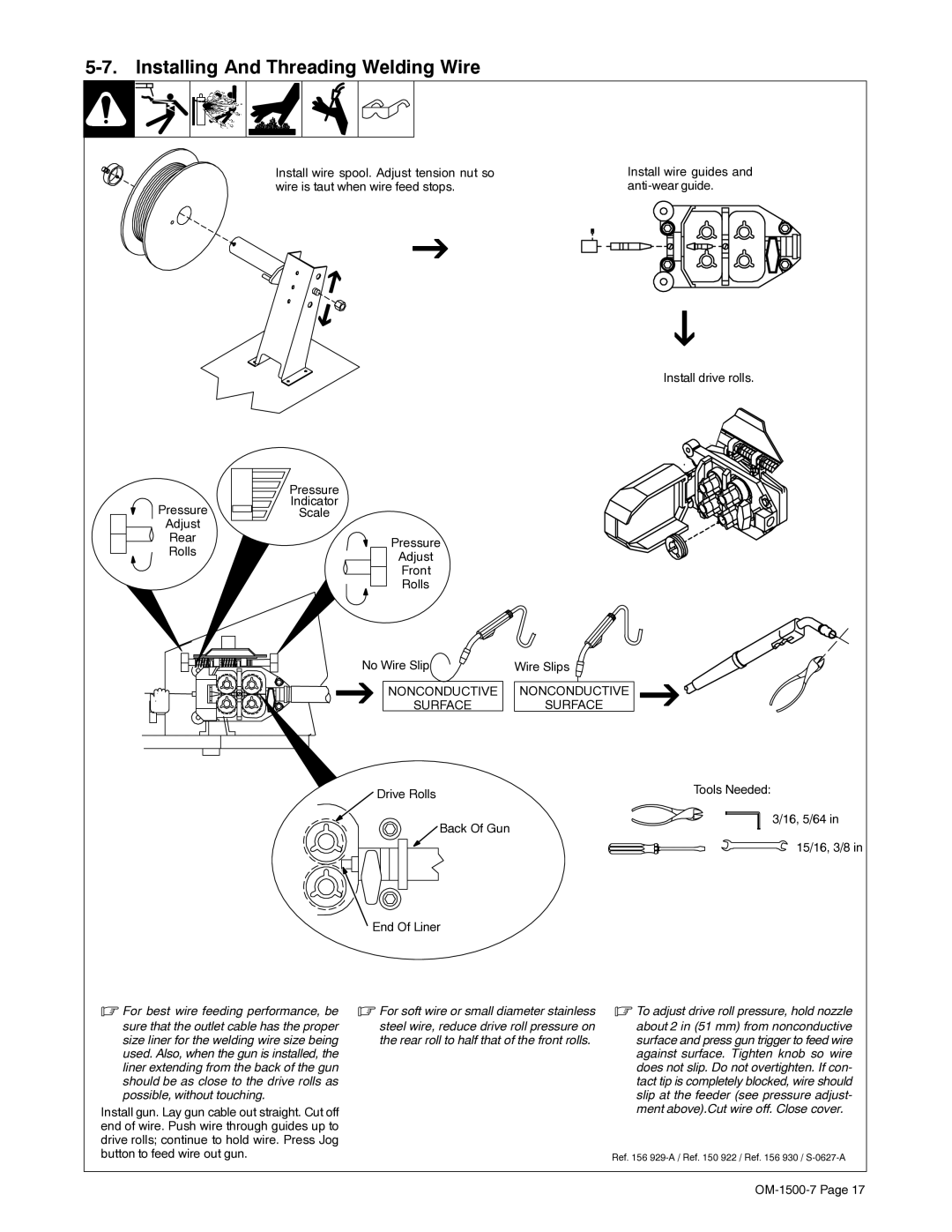
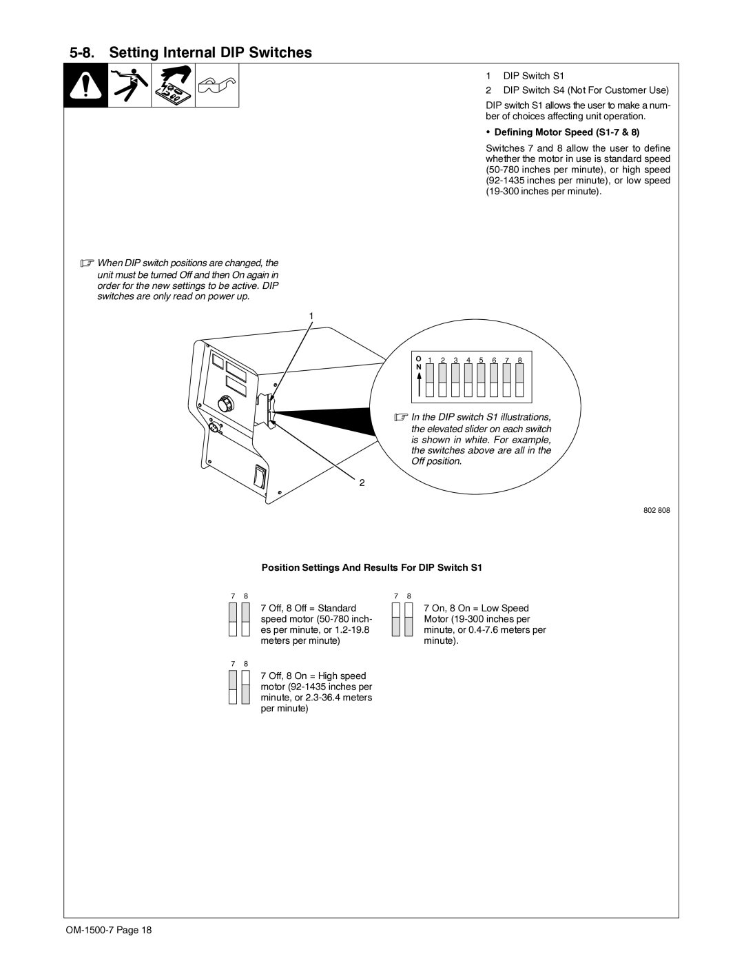
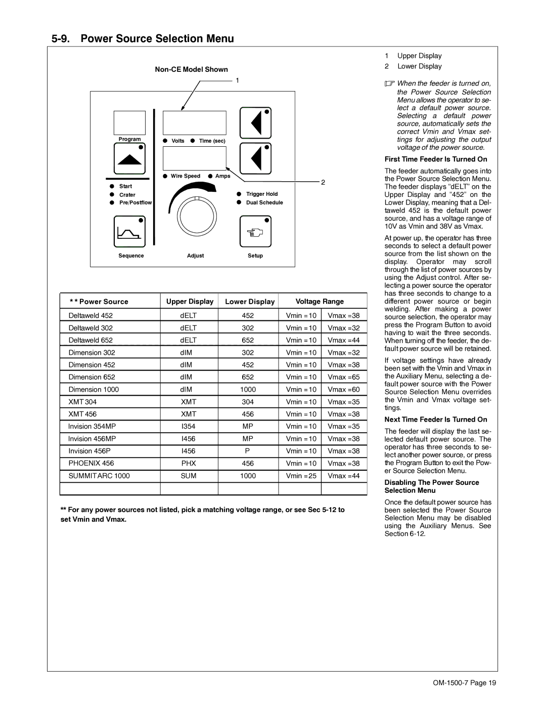
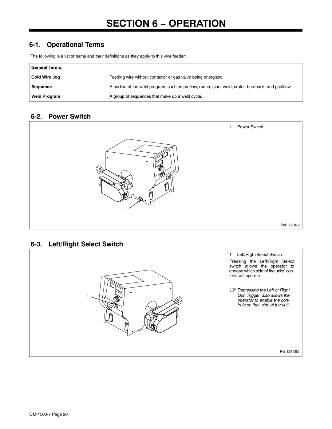
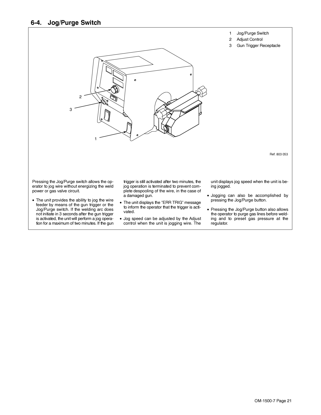
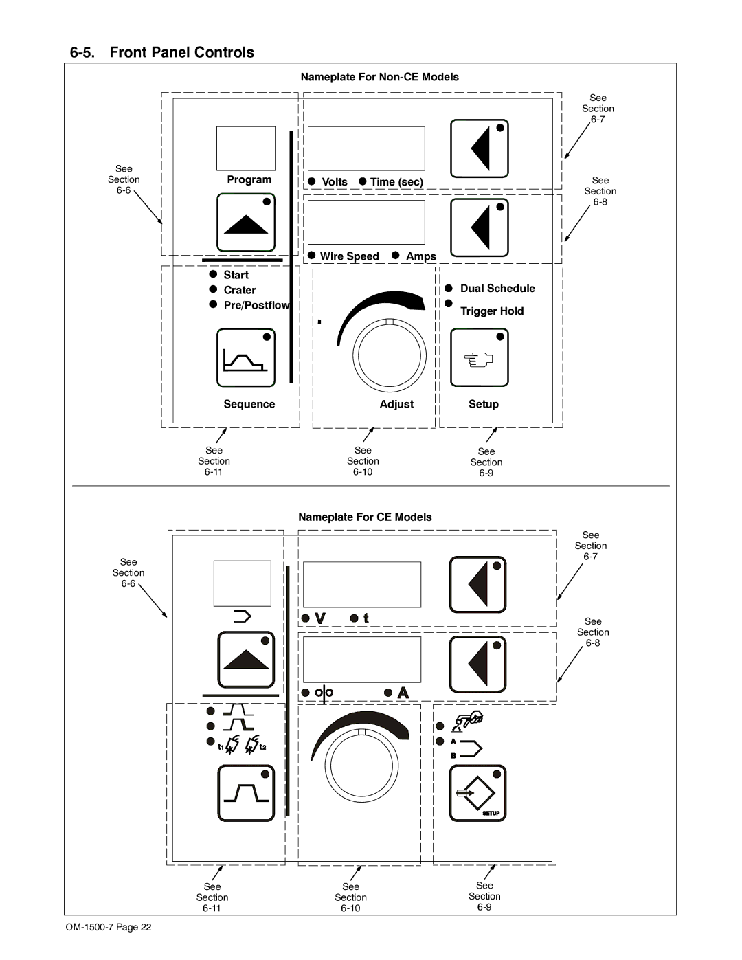
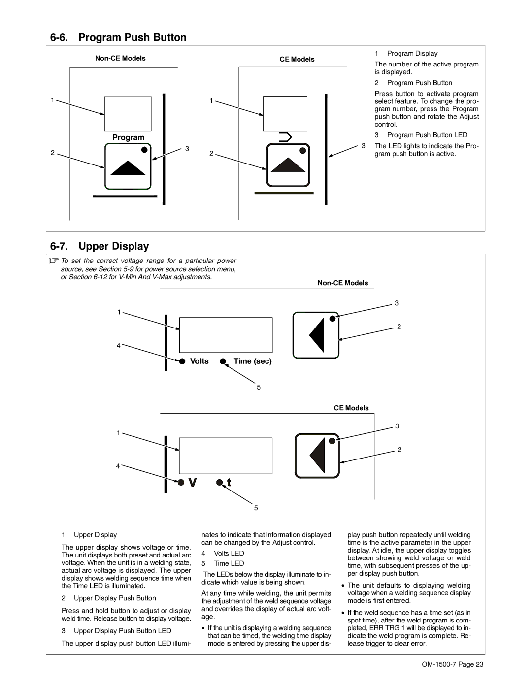
Contents OM-1500-7 204 129H ProcessesDescription File MIG GmawFrom Miller to You Table of Contents Directives Decwire6/05Standards Symbol Usage Arc Welding HazardsElectric Shock can kill HOT Parts can cause severe burnsFumes and Gases can be hazardous ARC Rays can burn eyes and skinWelding can cause fire or explosion Flying Metal or Dirt can injure eyesWelding Wire can cause injury Fire or Explosion hazardFalling Unit can cause injury Moving Parts can cause injuryPrincipal Safety Standards California Proposition 65 WarningsEMF Information About Implanted Medical DevicesUNE Décharge Électrique peut entraîner la mort Symboles utilisésIndique des instructions spécifiques LES Fumées ET LES GAZ peuvent être dangereux DES Pièces Chaudes peuvent provoquer des brûlures gravesLE Soudage peut provoquer un in cendie ou une explosion LE Bruit peut endommager l’ouïe LES Bouteilles peuvent exploser si elles sont endommagéesRisque D’INCENDIE OU D’EXPLO- Sion LA Chute DE L’APPAREIL peut blesserLES Fils DE Soudage peuvent provoquer des blessures Proposition californienne 65 AvertissementsLE Soudage À L’ARC risque de provoquer des interférences Information EMF Principales normes de sécuritéEn ce qui concerne les implants médicaux OM-1500-7 Drive rolls can injure fingers Disconnect input plug or power before working on machineKeep your head out of the fumes Symbols And Definitions Some symbols are found only on CE productsRating Label For CE Products Weee Label For Products Sold Within The EUSite Selection SpecificationsRating Shielding gas pressure not to Equipment Connection DiagramsExceed 100 PSI 689 kPa Rear Panel Connections And Rotating Drive Assembly Wire Type, Size, And Feed Speed Capability Table Motor Speed Wire Type Wire Size Feed Speed CapabilityPin Plug Information Gun Recommendation TableInstalling And Threading Welding Wire Ment above.Cut wire off. Close coverSetting Internal DIP Switches DIP Switch S1 DIP Switch S4 Not For Customer UseWhen DIP switch positions are changed, Position Settings And Results For DIP Switch S1Power Source Selection Menu Left/Right Select Switch Power SwitchOperational Terms Jog/Purge Switch Front Panel Controls Wire SpeedTime sec Program Push Button Upper DisplayNon-CE Models CE ModelsSetup Push Button Lower DisplayTime Welding Sequence Diagram Adjust ControlSequence Push Button Setup Push Button Auxiliary MenusSequence Push Button Upper DisplayReset To Factory Settings Power Source Selection MenuTrigger Hold Setup Wire Feed Speed UnitsSoftware Revision Level Display HoldCode Sequence Parameters In a Program Optional Dual Schedule Switch DiagramsFor more information on Sequence Push Button see Section Diagnostics ErrorLED3-Related Error Indications There is a two-position DIPRoutine Maintenance Diagnostics For User Defined OptionsMonths Troubleshooting Disconnect power before troubleshootingTrouble Remedy PullOM-1500-7 − Electrical Diagram 204 144-C − Parts List Part Description Quantity Control Box Harness Connectors/Receptacles PLG117 165See -1 For Drive Roll & Wire Guide Kits Hardware is common Not available unless listed21 . PC51,151 201 Drive Roll And Wire Guide Kits Fraction Metric Kit Roll Wire SizeRoll Drive Roll Drive KitYour distributor also gives ServiceSupport To locate a Distributor or Service Agency visit Miller Electric Mfg. CoFor assistance in filing or settling claims, contact Your distributor and/or equipment manufacturer’s