HP Accessing the Management Tool at 192.168.5.11 for Your Network Router

Page 22

Getting started

Scenario 1: Connecting wired devices to a wireless network

6.Select Save. The IP address of the M111 will immediately change, causing you to lose your connection to the management tool. This is normal. To re-establish the connection, configure the computer with a static IP address on the same subnet as the M111. For this scenario, use 192.168.5.12.


Port

1


.11


.5


port


.168


LAN

.12

192


.5


.168


192


7.Re-launch the management tool by browsing to the new IP address assigned to the M111: https://192.168.5.11.

F.Configure a station profile

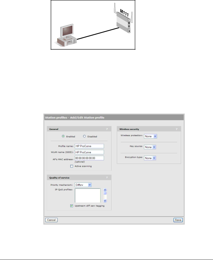
A station profile contains the settings that the M111 uses to establish a connection with a wireless network. This section explains how to customize the default station profile that is pre-configured on the M111.

1.Select Wireless > Station profiles and select the HP ProCurve profile in the table. The Add/Edit Stations profile page opens.

2-6

Image 22
Contents ProCurve 5400zl Switches HP ProCurve M111 Client Bridge Page HP ProCurve M111 Client Bridge Publication Number Contents Working with the M111 Field descriptions To assign a management address Resetting to factory defaults Regulatory informationViii Introduction Important terms About this guideProducts covered ConventionsCommands and program listings Example DescriptionKey features Introducing the M111 Client BridgeProfessional Installation Required Safety informationServicing Online documentation HP ProCurve Networking supportBefore contacting support Getting started Deploying the M111 Scenario 1 Connecting wired devices to a wireless networkOverview Configuration procedure Configure your computerConnect to the M111 Passwords Select Network DNSConfigure a station profile Connect the wired computers to the M111  The printer is configured with a static IP address Configure MAC cloning options Connect the wired device to the M111 Scenario 3 Connecting a serial device to a wireless network Configure the serial connection Getting started Getting started Working with the M111 802.1X certificates Certificate stores Certificate usage Management tool About passwordsStarting the management tool Customizing management tool settings Manager and Operator accountsPasswords Security policies SecurityWeb server IP address configurationAuto-refresh To configure IP addressing Radio configuration Wireless rangeWireless mode To configure the radioRestrict channels to Antenna selection Fast roaming threshold Fast roaming delta thresholdFast roaming threshold count Scan channel delayFast scan channel delay Minimum SNR thresholdTransmit power control Using station profiles to establish a wireless linkAdvanced wireless settings RTS thresholdWorking with the M111 To add or edit a station profile GeneralKey source Wireless securityWireless protection EAP methodWorking with the M111 Encryption type Quality of serviceViewing APs in the neighborhood Ap1certificate or ap2certificateAccess category Configuring Quality of Service QoSField descriptions Priority mechanisms QoS settings in a station profile802.1p Differentiated Services DiffServ Very-high, high, normal, low priorityTo define an IP QoS profile DisabledCreating IP QoS profiles Upstream DiffServ taggingProfile name Connecting serial devicesSettings Protocol Start port/ End portSerial port connector To connect a serial deviceMode Transmit timeoutIdle timeout Remote IP addressParity bit Drop wireless link when port 1 is connectedData bits Stop bitsTx kbytes DNS configurationConnection time Rx kbytesOverride dynamically assigned DNS servers DNS switch on server failureDynamically assigned DNS servers ServerHandling unsupported traffic DNS switch overEnable the Redirect unsupported traffic to option To forward unsupported trafficIP forwarding Cloning the address of a wired deviceLimitations Wireless access to the M111 when MAC cloning is active Enabling Ethernet MAC cloningSnmp agent UDP port Setting up management traffic interceptionManagement tool TCP port Select Management SnmpSnmp notifications UDP port Using filters to restrict wireless trafficEnable the Wireless traffic filters option Remote log UDP portAssigning a management address To assign a management addressSnmp V1/v2c communities AttributesV3 users Managing certificates Notification receiversInstall 802.1X Install TLS client certificatePassword 802.1X certificates802.1X Trusted CA certificates Certificate stores802.1X Manage TLS client certificates 802.1X Manage CA certificatesTrusted CA certificate store Installing a new CA certificateCA certificate import formats Certificate and private key store END CertificateSpecify the Pkcs #12 password Default installed private key/public key certificate chainsCertificate usage Changing the certificate assigned to a service About certificate warningsManual configuration file management Configuration file managementBackup configuration Restore configuration Reset configurationScheduled operations Software updates Select Install Performing an immediate software updatePerforming a scheduled update Enable Scheduled installWorking with the M111 Regulatory information Manufacturers FCC Declaration of Conformity Statement Countries of Operation & Conditions of Use Operation Using 5 GHz Channels in the European Community GHz OperationIndoor or outdoor use 1000 124, 128, 132, 136 Supported External Antennas5470 Antenna Band GHzDGT LPD Low Power Device Statement Resetting to factory defaults Using the management tool Using the Reset buttonHow it works Page Technology for better business outcomes