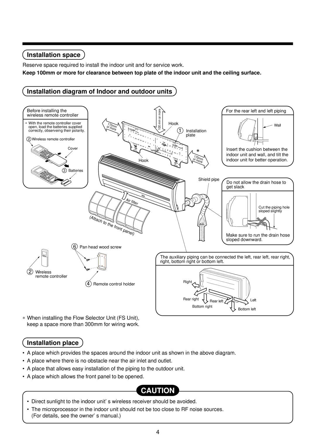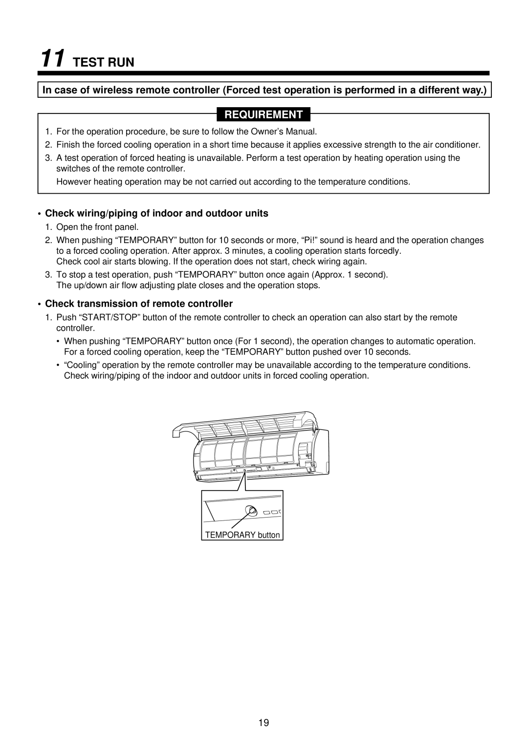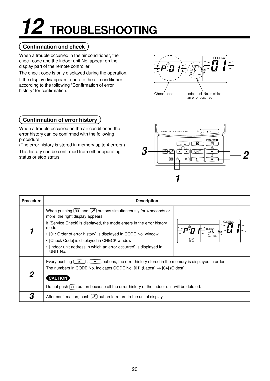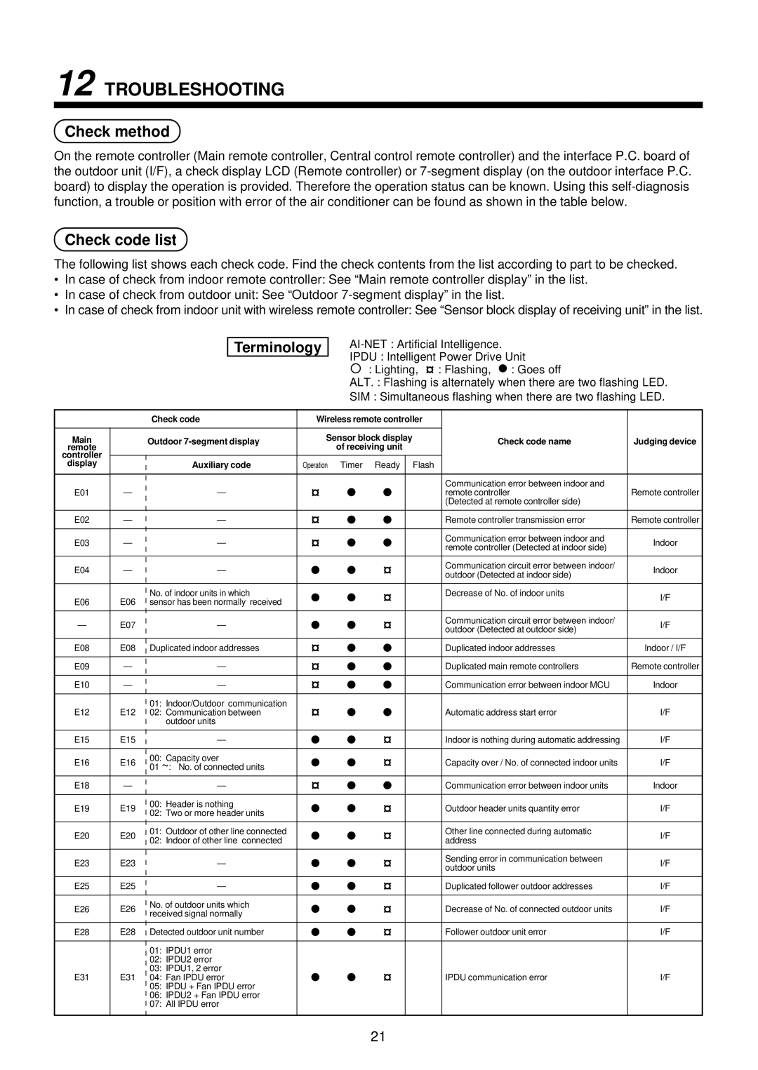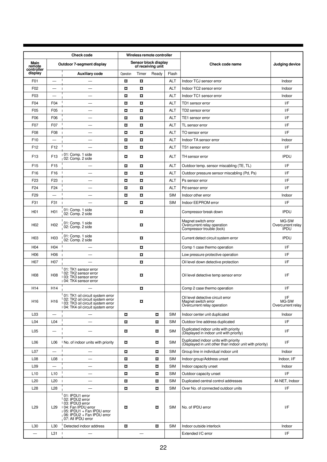
4 CUTTING A HOLE AND MOUNTING INSTALLATION PLATE
Cutting a hole
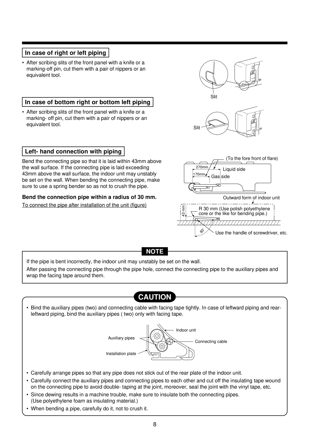
In case of installing the refrigerant pipes from the rear:
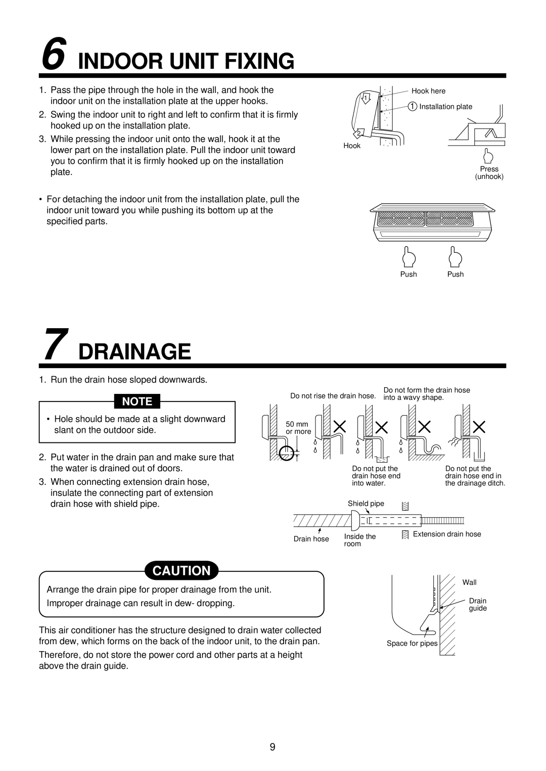
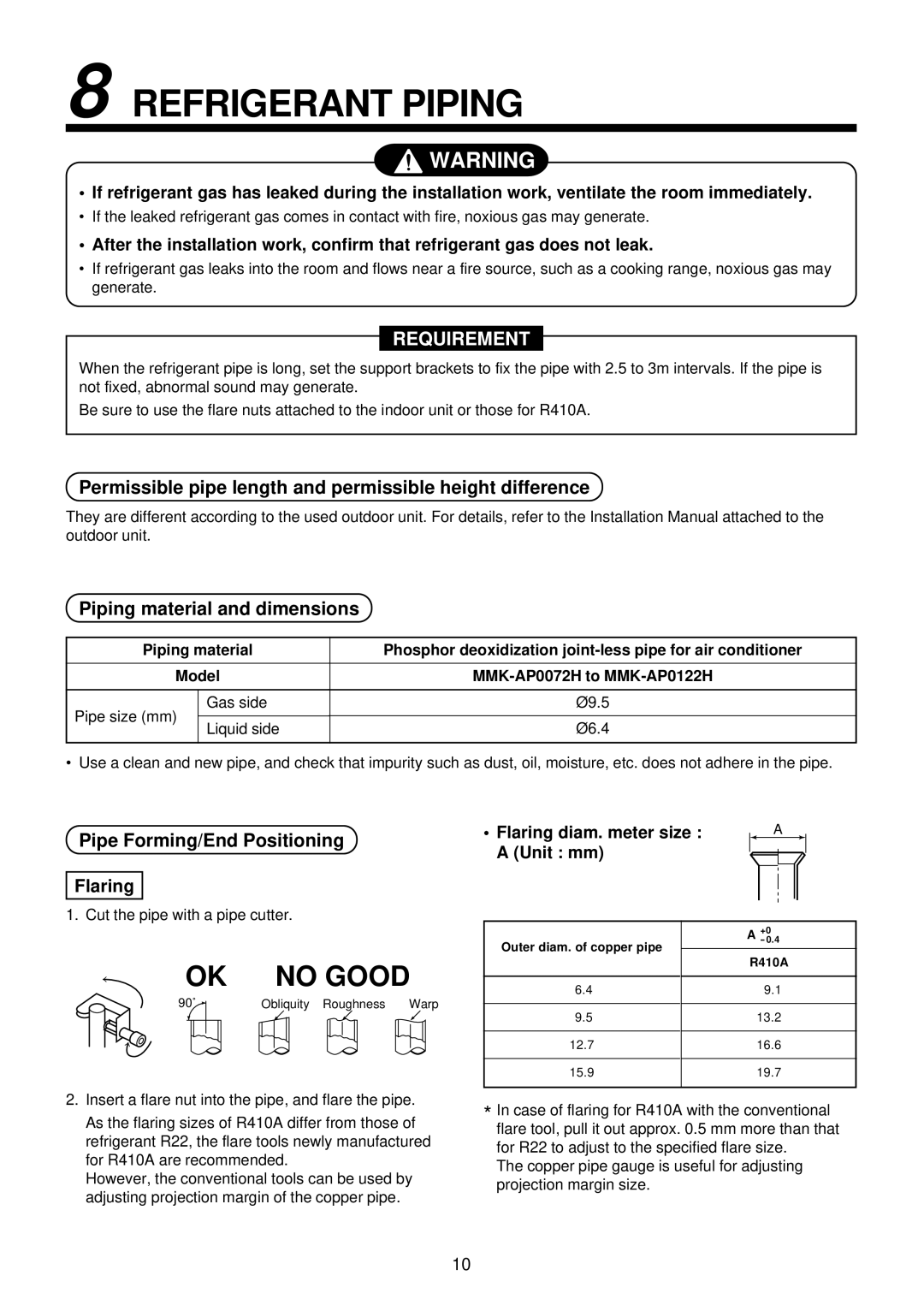
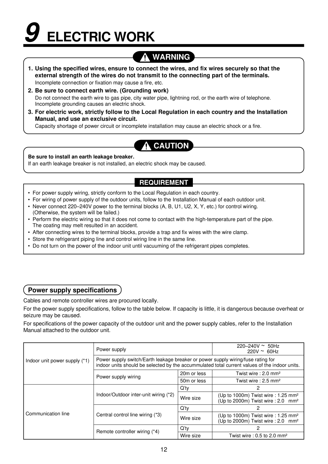
1.Decide the hole position for piping at 100mm from the arrow mark ( ![]() ) on the installation plate and drill a hole with Ø65mm at a slight downward slant toward outdoor side.
) on the installation plate and drill a hole with Ø65mm at a slight downward slant toward outdoor side.
The center of the pipe hole is above the arrow.
Pipe hole
65 mm
100 mm
NOTE
•When drilling a wall that contains a metal lath, wire lath or metal plate, be sure to use a pipe hole brim ring sold separately.
Mounting the installation plate
107 127.5
Hook
For installation of the indoor unit,
use the paper pattern in the accessory parts.
170 |
|
|
| |
85 |
|
|
| |
|
|
| 1 | |
|
| Hook | Installation | |
| Thread | plate | ||
Pipe hole | Pipe hole | |||
Hook | 5 Mounting screw | |||
| ||||
|
| |||
Indoor unit | Weight |
| ||
When the installation plate is directly mounted on the wall
1.Securely fit the installation plate onto the wall by screwing it in the upper and lower parts to hook up the indoor unit.
2.To mount the installation plate on a concrete wall with anchor bolts, utilize the anchor bolt holes as illustrated in the above figure.
3.Install the installation plate horizontally in the wall.
CAUTION
When installing the installation plate with a mounting screw, do not use the anchor bolt hole.
Otherwise the unit may fall down and result in personal injury and property damage.
NO | OK NO | Anchor bolt |
GOOD | GOOD |
5mm dia. hole
Projection ![]() 15mm or less
15mm or less
7 Mounting screw Ø4 × 25 ![]()
![]() Clip anchor (local parts)
Clip anchor (local parts)
CAUTION
Failure to firmly install the unit may result in personal injury and property damage if the unit falls.
•In case of block, brick, concrete or similar type walls, make 5mm dia. holes in the wall.
•Insert clip anchors for appropriate … mounting screws.
NOTE
• Secure four corners and lower parts of the installation plate with 4 to 6 mounting screws to install it.
6


