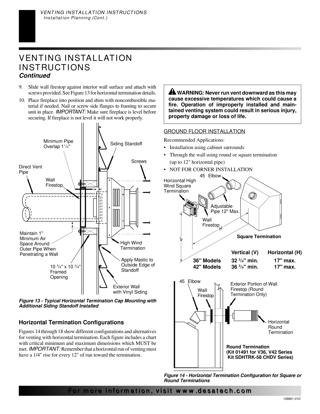
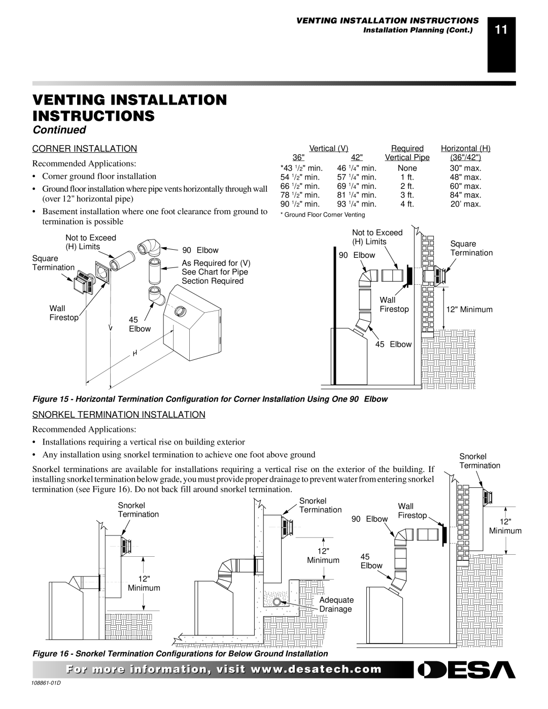
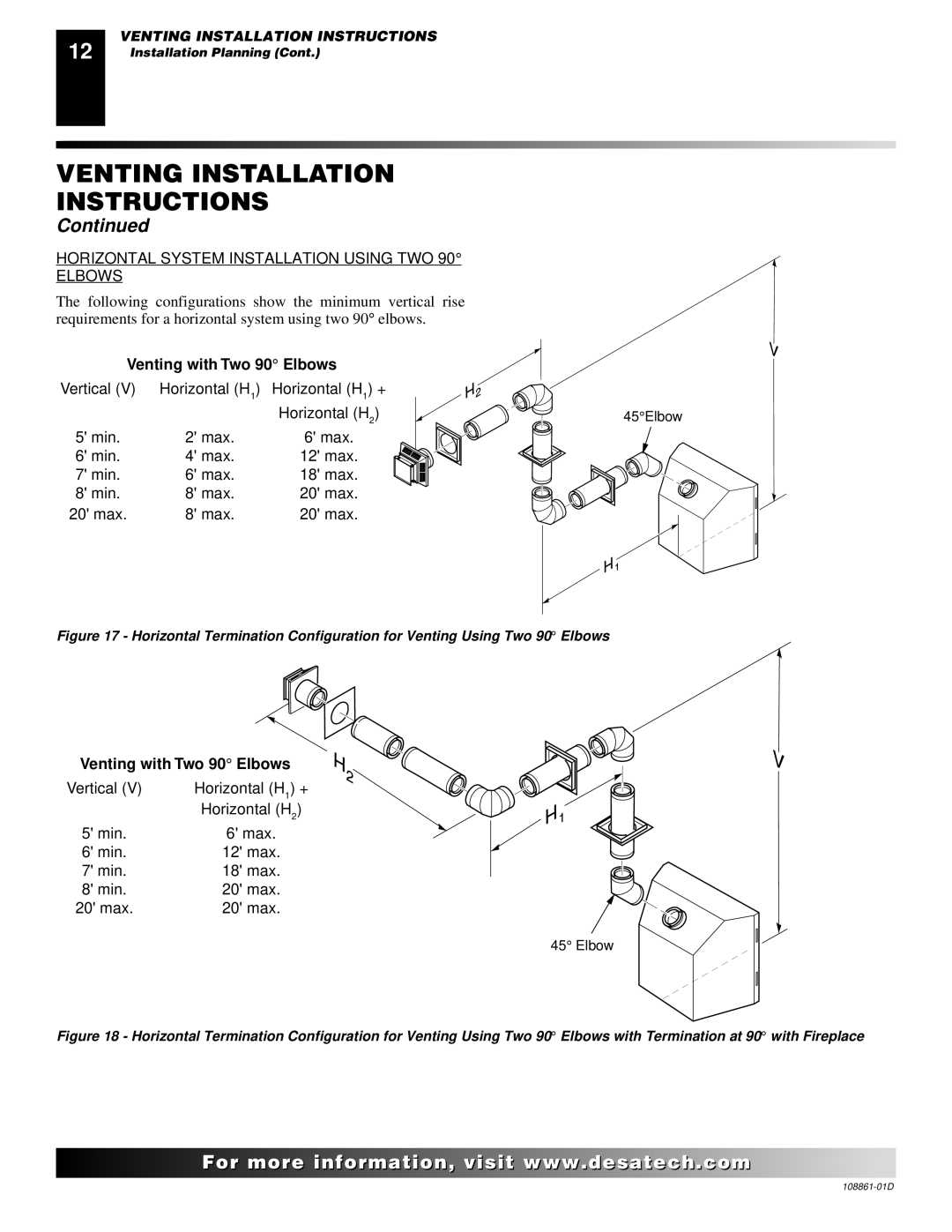
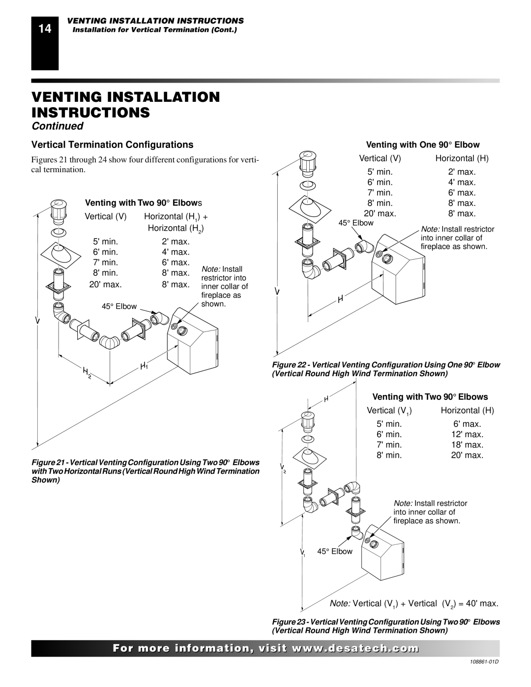
Desa CHDV36NR, (V)V42P, (V)V42N, (V)V36P, CHDV42NR Model BKT Installation, Blower Model BKT

Page 18

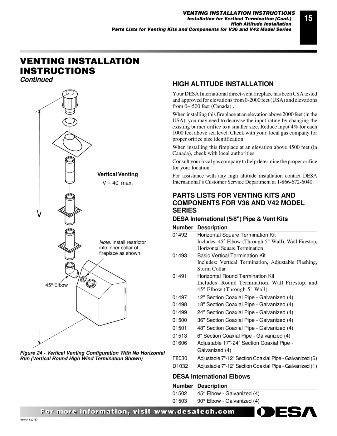
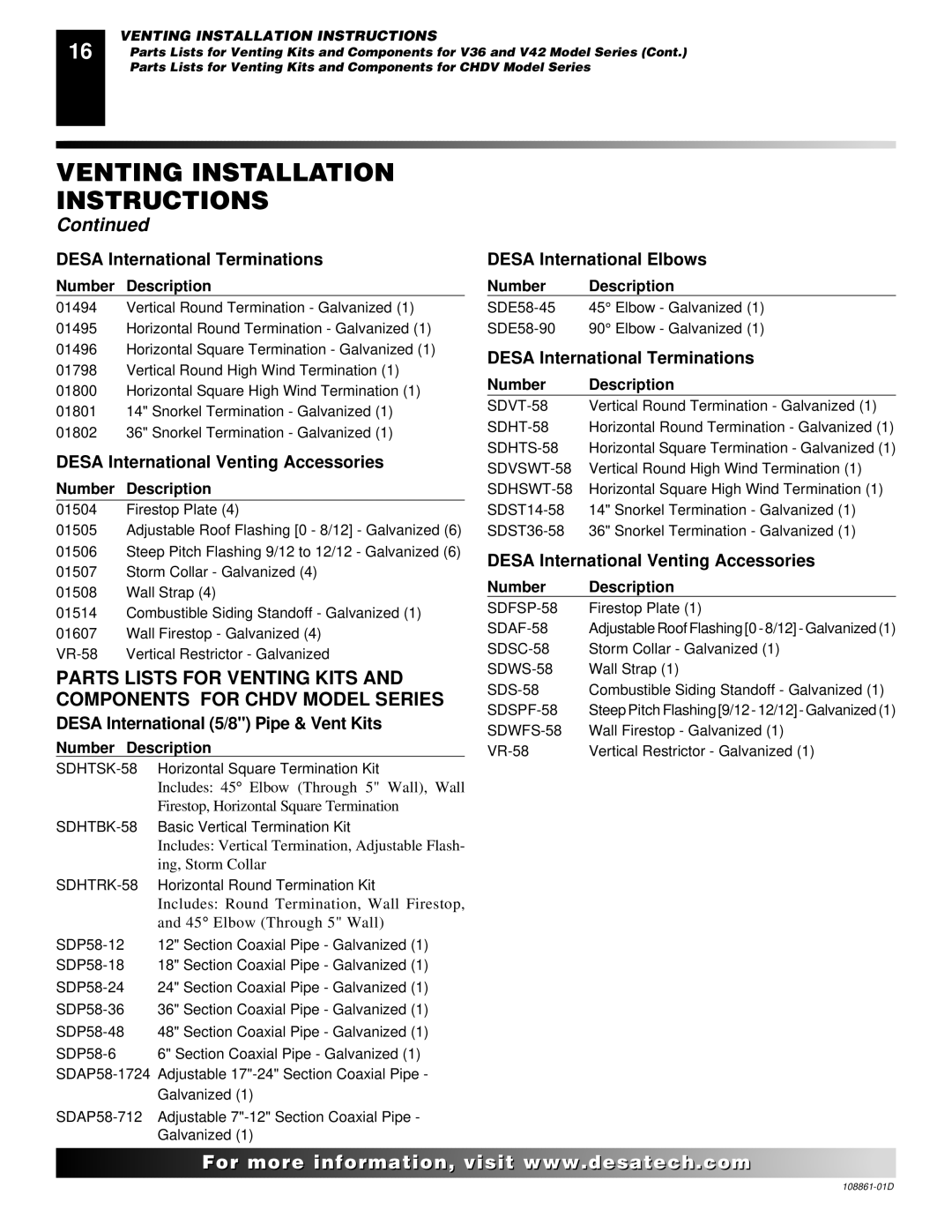
18

FIREPLACE INSTALLATION

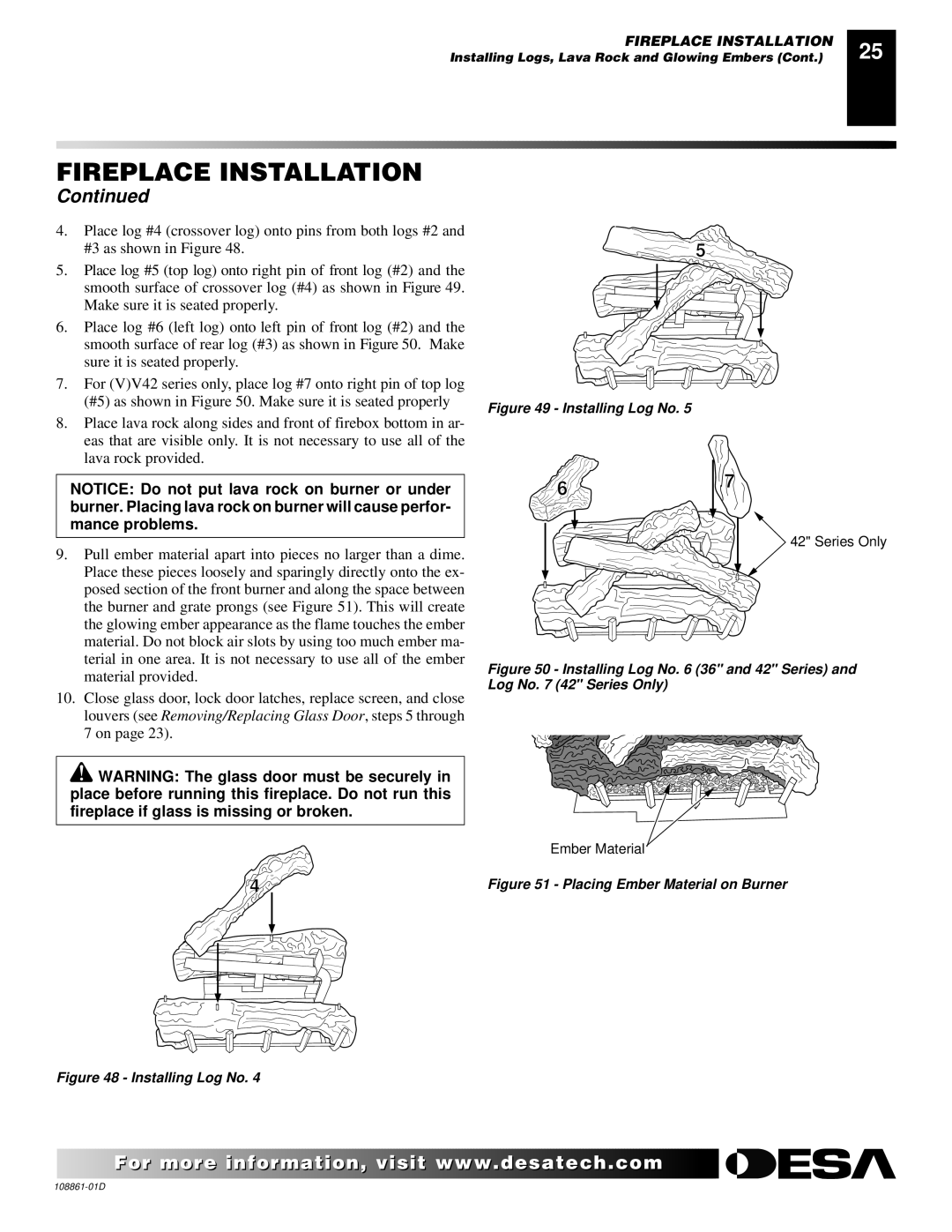
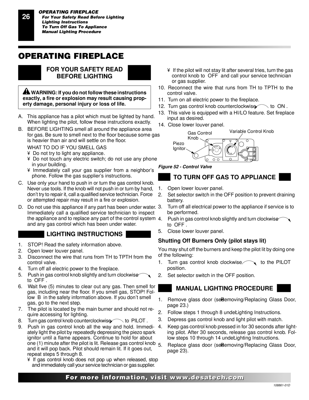
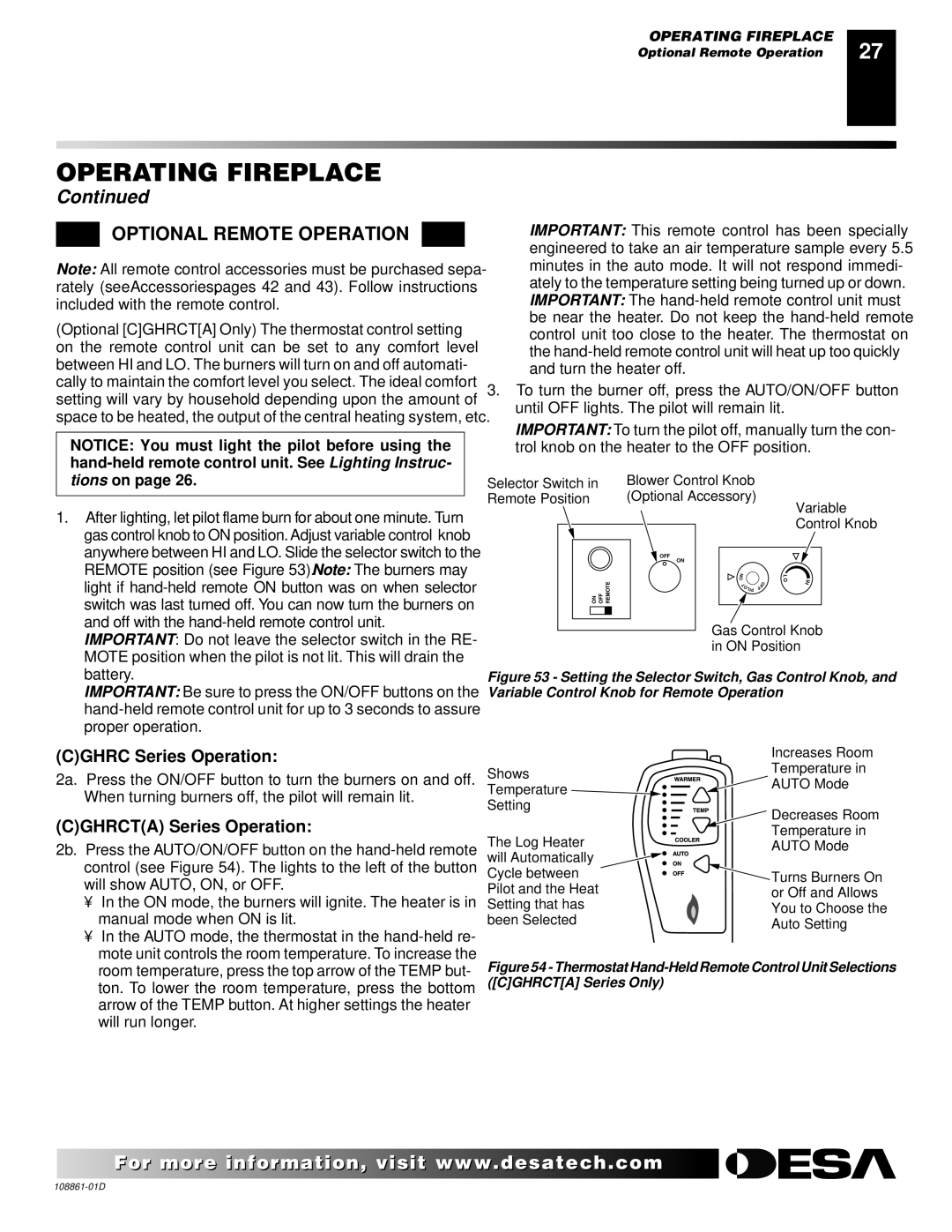
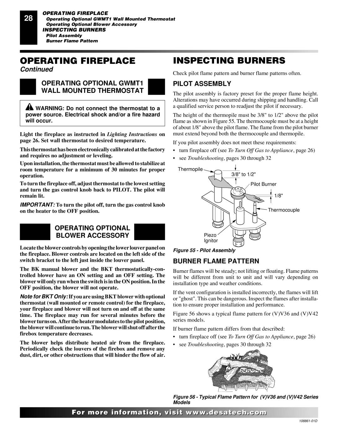
Installing Optional Blower Accessories (Cont.)

FIREPLACE INSTALLATION

Continued

9.Check to make sure that the power cord is completely clear of the blower wheel and that there are no other foreign objects in blower wheel. Turn blower on and check for operation. Turn blower off by turning knob fully counterclockwise before continuing.

10.Peel off the backing paper and stick the supplied wiring dia- gram decal on the firebox bottom approximately 12" in front of the blower (see Figure 27).

Wiring Diagram Decal

12" in Front of Blower

Figure 27 - Location of Wiring Diagram Decal (Model May Vary From Illustration)

Model BKT Installation

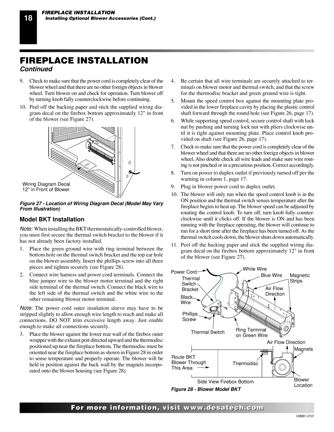
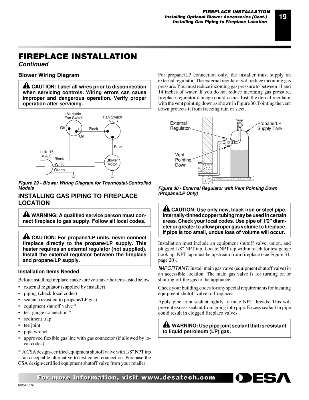
Note: When installing the BKT thermostatically-controlled blower, you must first secure the thermal switch bracket to the blower if it has not already been factory installed.

1.Place the green ground wire with ring terminal between the bottom hole on the thermal switch bracket and the top ear hole on the blower assembly. Insert the phillips screw into all three pieces and tighten securely (see Figure 28).

2.Connect wire harness and power cord terminals. Connect the blue jumper wire to the blower motor terminal and the right side terminal of the thermal switch. Connect the black wire to the left side of the thermal switch and the white wire to the other remaining blower motor terminal.

Note: The power cord outer insulation sleeve may have to be stripped slightly to allow enough wire length to reach and make all connections. DO NOT trim excessive length away. Just enable enough to make all connections securely.

3.Place the blower against the lower rear wall of the firebox outer wrapper with the exhaust port directed upward and the thermodisc positioned up near the fireplace bottom. The thermodisc must be oriented near the fireplace bottom as shown in Figure 28 in order to sense temperature and properly operate. The blower will be held in position against the back wall by the magnets incorpo- rated onto the blower housing (see Figure 28).

4.Be certain that all wire terminals are securely attached to ter- minals on blower motor and thermal switch, and that the screw for the thermodisc bracket and green ground wire is tight.

5.Mount the speed control box against the mounting plate pro- vided in the lower fireplace cavity by placing the plastic control shaft forward through the round hole (see Figure 26, page 17).

6.While supporting speed control, secure control shaft with lock nut by pushing and turning lock nut with pliers clockwise un- til it is tight against mounting plate. Place control knob pro- vided on shaft (see Figure 26, page 17).

7.Check to make sure that the power cord is completely clear of the blower wheel and that there are no other foreign objects in blower wheel. Also double check all wire leads and make sure wire rout- ing is not pinched or in a precarious position. Correct accordingly.

8.Turn on power to duplex outlet if previously turned off per the warning in column 1, page 17.

9.Plug in blower power cord to duplex outlet.

10.The blower will only run when the speed control knob is in the ON position and the thermal switch senses temperature after the fireplace begins to heat up. The blower speed can be adjusted by rotating the control knob. To turn off, turn knob fully counter- clockwise until it clicks off. If the blower is ON and has been running with the fireplace operating, the blower will continue to run for a short time after the fireplace has been turned off. As the thermal switch cools down, the blower shuts down automatically.

11.Peel off the backing paper and stick the supplied wiring dia- gram decal on the firebox bottom approximately 12" in front of the blower (see Figure 27).

Power Cord

White Wire

Blue Wire Magnetic

Thermal

Strips

Switch

Air Flow

Bracket

Black

Direction


Wire


Phillips


Screw


Thermal Switch

Ring Terminal

on Green Wire


Air Flow Direction


Magnets

Route BKT


Blower Through

Thermodisc

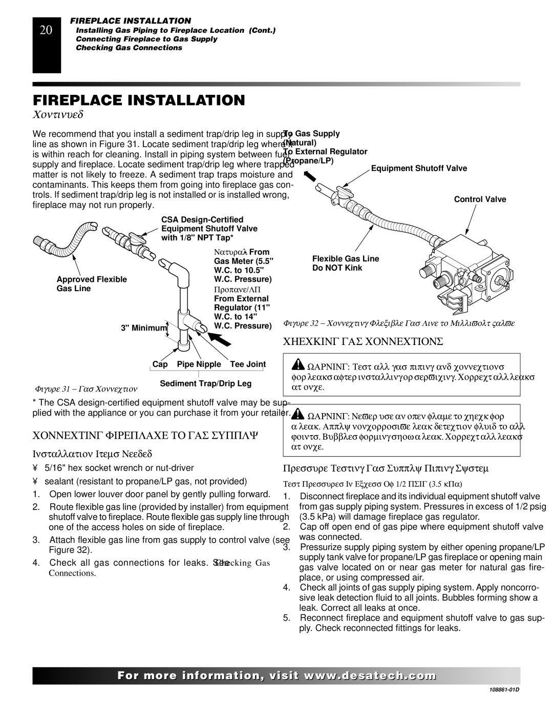
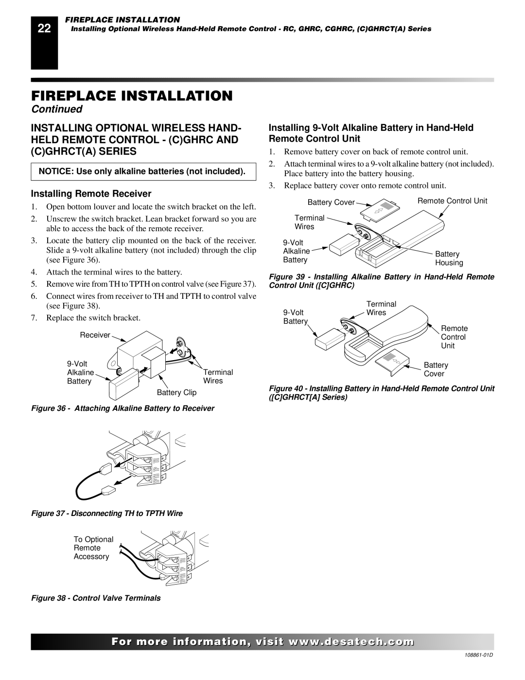
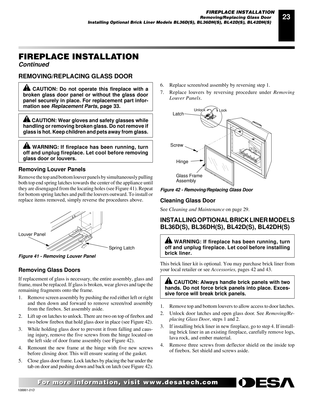
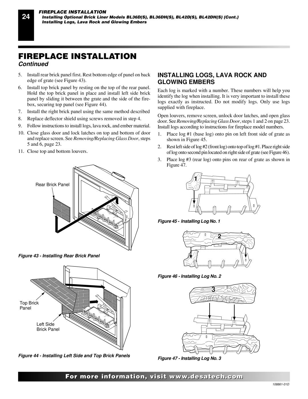
This Area


Side View Firebox Bottom

Blower

Location

Figure 28 - Blower Model BKT


For..com

108861-01D

Image 18
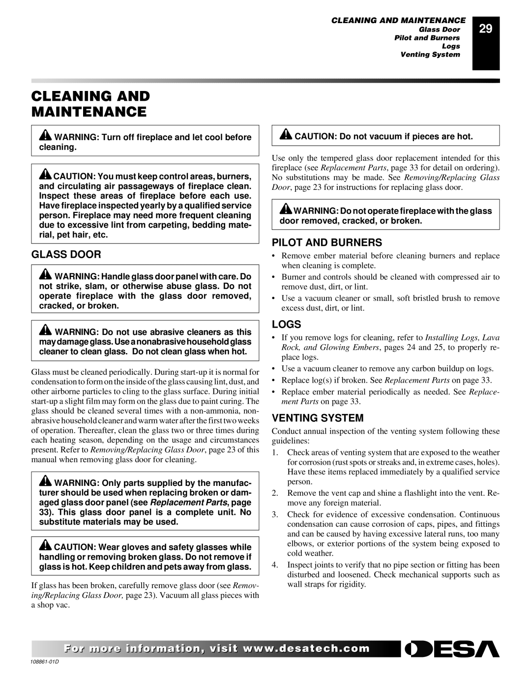
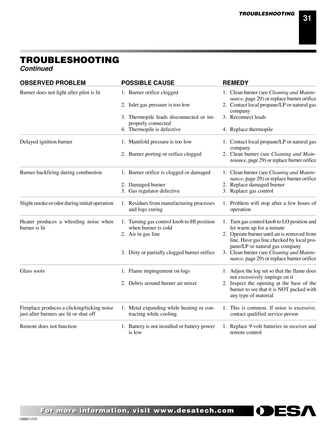
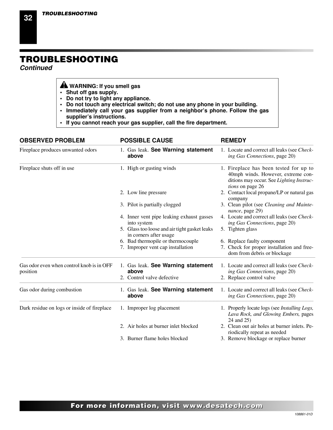
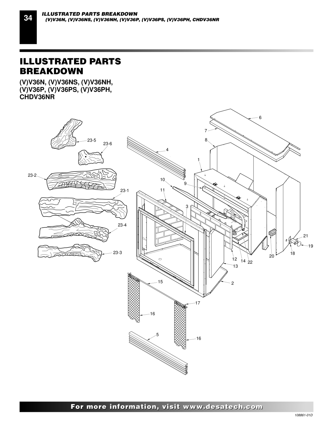
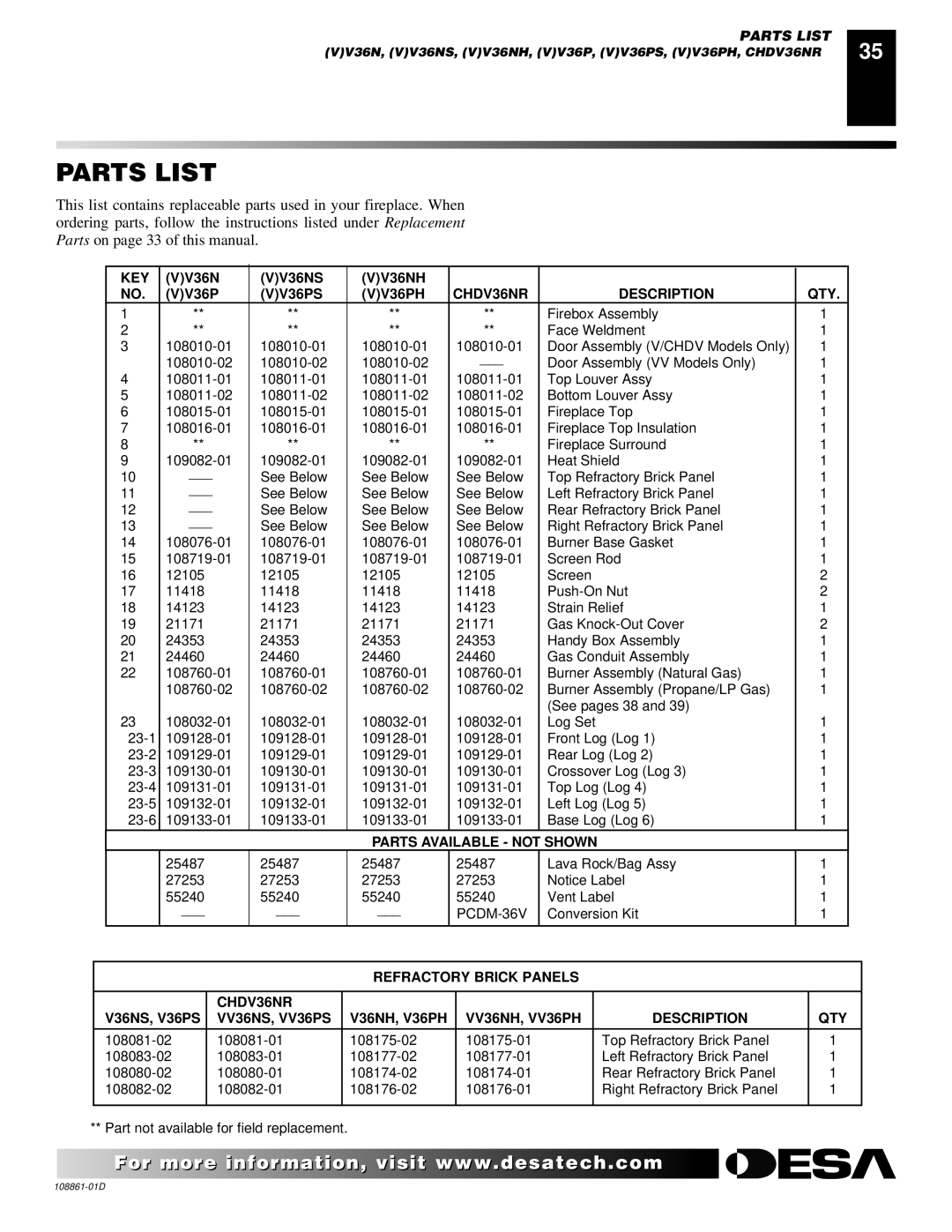
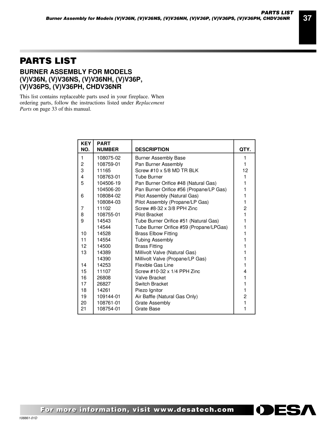
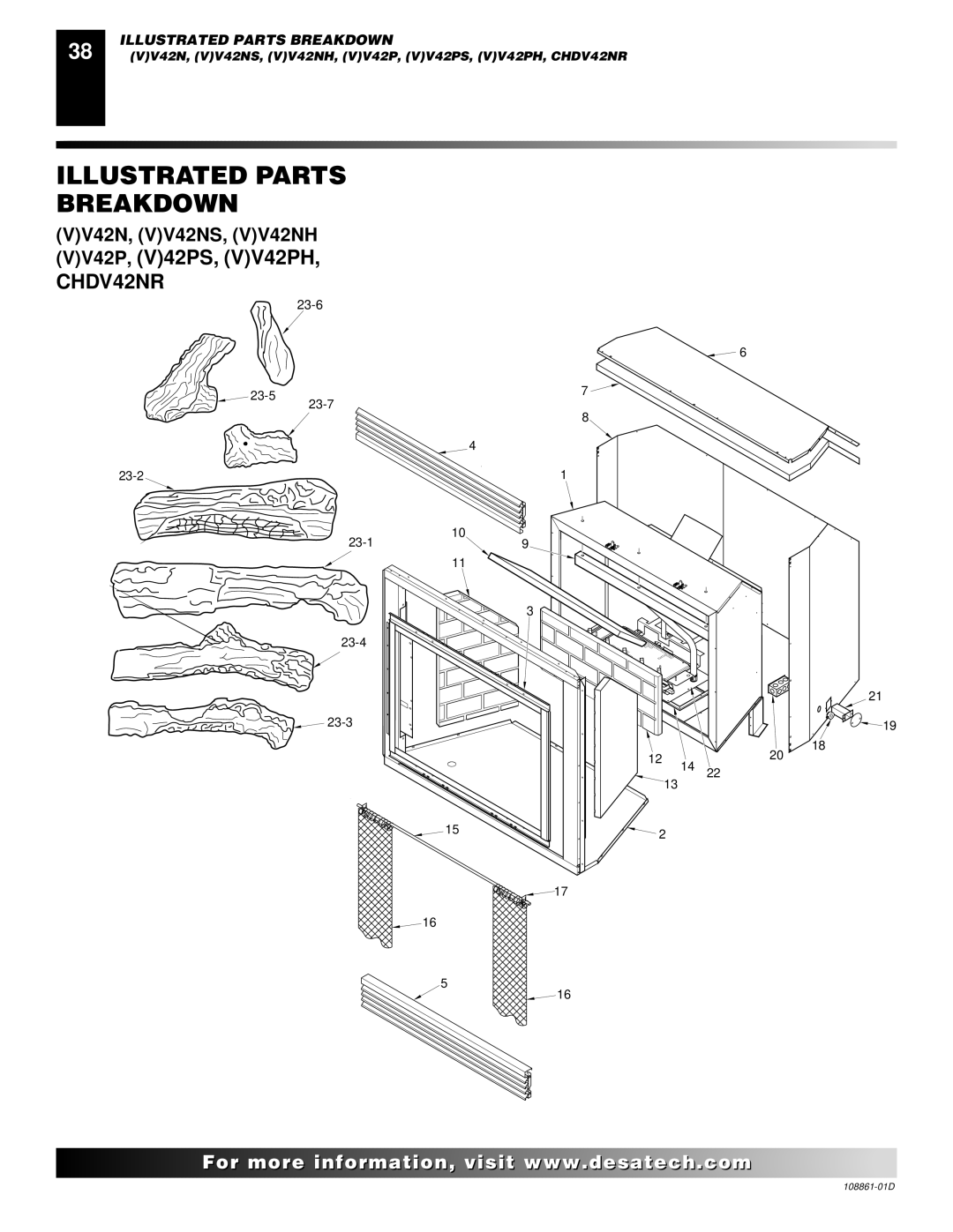
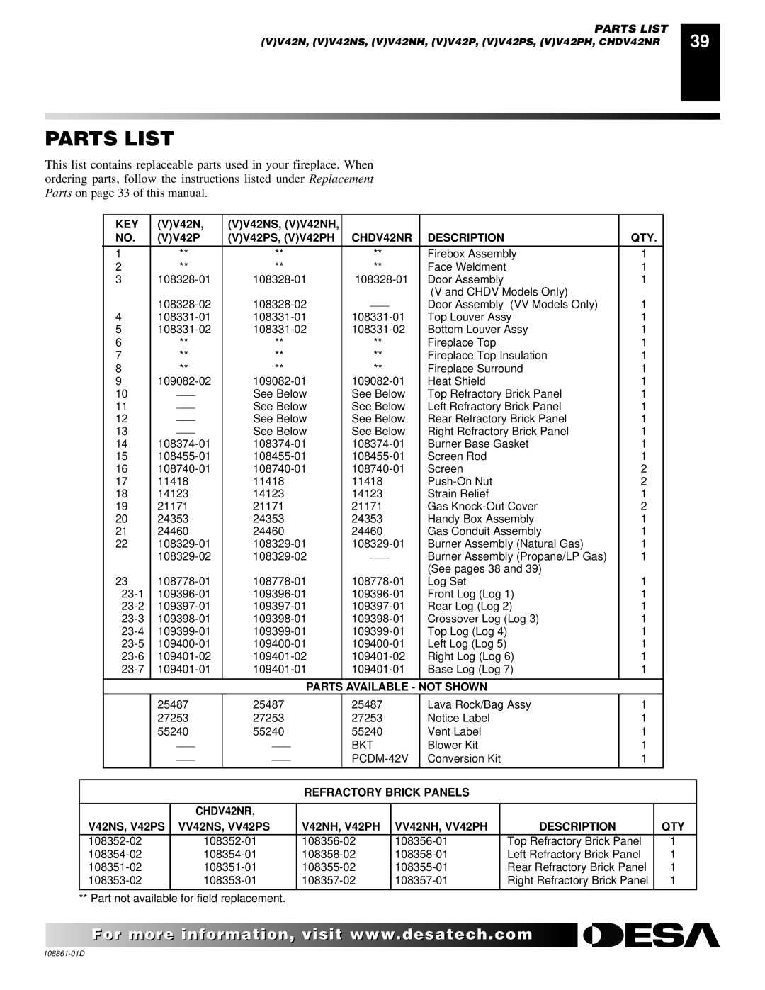
Contents TM OWNER’S Operation Installation Manual For Your SafetyFor Your Safety What to do if YOU Smell GAS Table of Contents Safety InformationSafety Information Product Identification Local CodesProduct Features PRE-INSTALLATION PreparationLocation and Space Requirements Clearances Framing and FinishingLocation of Termination CAP Balcony with Perpendicular Side WallVenting Installation Instructions Installation PrecautionsInstallation Planning Horizontal Termination InstallationInstalling Siding Standoff Horizontal Termination Configurations Vertical Horizontal H Models 32 3/ 4 minModels 36 3/ 4 min Corner Installation Horizontal System Installation Using TWO 90 Elbows Venting with Two 90 ElbowsInstallation for Vertical Termination Flat Ceiling InstallationVertical Termination Configurations Venting with One 90 ElbowDesa International Elbows High Altitude InstallationDesa International 5/8 Pipe & Vent Kits Vertical VentingDesa International Venting Accessories Desa International TerminationsModel BK Installation Fireplace InstallationInstalling Optional Blower Accessories Check GAS TypeModel BKT Installation Blower Model BKTInstalling GAS Piping to Fireplace Location Blower Wiring DiagramInstallation Items Needed Pressure Testing Gas Supply Piping System Connecting Fireplace to GAS SupplyInstallation Items Needed Checking GAS ConnectionsPressure Testing Fireplace Gas Connections Checking Gas Joints for Propane/LP Gas FireplaceReplace the switch bracket Removing Louver Panels Cleaning Glass DoorREMOVING/REPLACING Glass Door Removing Glass DoorsInstalling LOGS, Lava Rock and Glowing Embers Installing Rear Brick PanelInstalling Log No 36 and 42 Series and Log No 42 Series Only Operating Fireplace For Your Safety Read Before LightingManual Lighting Procedure Lighting InstructionsOptional Remote Operation Cghrc Series OperationCghrcta Series Operation Inspecting Burners Operating Optional Blower AccessoryPilot Assembly Operating Optional GWMT1 Wall Mounted ThermostatPilot and Burners Cleaning MaintenanceGlass Door LogsTroubleshooting Observed Problem Possible CauseObserved Problem Possible Cause Remedy Gas leak. See Warning statement AboveTechnical Service Replacement PartsService Hints SpecificationsIllustrated Parts Breakdown Parts List CHDV36NR Description QTYIllustrated Parts Breakdown KEY Part Number Description QTY VV42P, V42PS, VV42PH, CHDV42NR Refractory Brick Panels CHDV42NR Illustrated Parts Breakdown KEY Part Number Description QTY Accessories Receiver and HAND-HELD ON/OFF Remote Control KIT Ghrc Series Wall Mounted Thermostat ControlWarranty Information

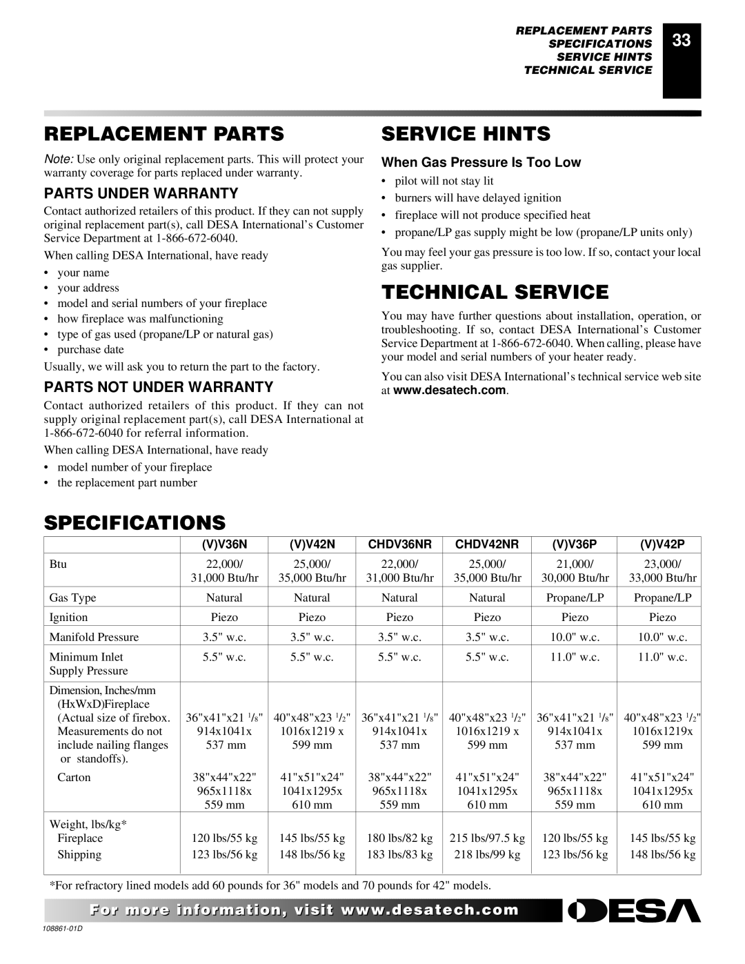
(V)V42P, CHDV42NR, (V)V36P, (V)V42N, CHDV36NR specifications

Desa (V)V42N, CHDV36NR, (V)V36P, (V)V42P, and CHDV42NR represent a range of cutting-edge technological innovations designed for modern heating solutions. These models exemplify the combination of efficiency, versatility, and advanced control features that cater to diverse user needs in both residential and commercial spaces.

One of the standout features of these models is their energy efficiency. Utilizing the latest in burner technology, they are engineered to provide robust heating with minimal fuel consumption. This not only helps in reducing energy bills but also supports environmentally friendly practices by lowering carbon emissions.

The Desa (V)V42N model is particularly notable for its smart thermostat compatibility. It allows users to integrate their heating system with smart home technologies, enabling remote access and control via mobile applications. This feature ensures users can monitor and adjust their heating settings from anywhere, enhancing convenience and comfort.

In contrast, the CHDV36NR model is designed with a focus on aesthetics and ambiance. This model incorporates a modern design with sleek finishes that can seamlessly blend into various interior styles. Its unique viewing window offers a stunning display of flames, creating a captivating focal point in any room.

For those looking for adaptable heating solutions, the (V)V36P and (V)V42P models are equipped with modular capabilities. These designs allow for easy installation and expansion, accommodating different room sizes and heating needs. Moreover, they feature advanced fan systems that distribute heat evenly, ensuring consistent warmth throughout the space.

The CHDV42NR brings another layer of technology with its dual-fuel capability, allowing users to choose between natural gas and propane. This flexibility is particularly advantageous in regions where fuel availability may vary, ensuring reliable performance regardless of the energy source.

Overall, the Desa (V)V42N, CHDV36NR, (V)V36P, (V)V42P, and CHDV42NR models showcase a robust combination of efficiency, advanced technology, and user-friendly features. Whether enhancing indoor comfort with smart technology, aesthetics, or adaptability, these products set a benchmark in the heating solution market. They are perfect for those seeking reliable performance and modern design in their heating systems.