Initial Installation
QUALIFIED INSTALLERS ONLY
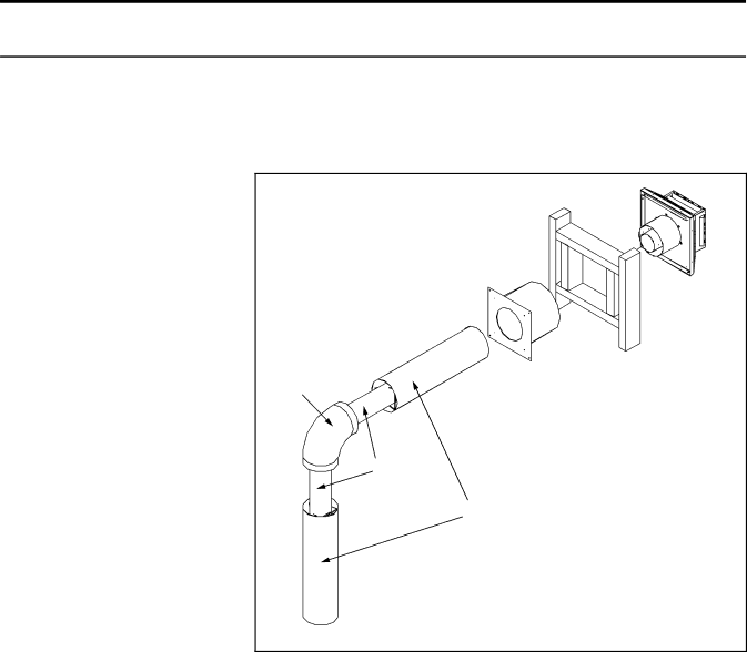
HORIZONTAL TERMINATION:
NOTES:
1.Horizontal pipes must not be level. For every 12 inches (305 mm) of horizontal travel (away from the stove), there should be at least 1⁄4 inch (6.4 mm) of vertical travel. Never allow the vent to run downward, as this could cause high temperatures or even present the possibility of a fire.
2. The exterior of the horizontal |
|
| ||||||||||
vent termination must not be |
|
| ||||||||||
blocked or obstructed. |
|
|
|
| ||||||||
3. If the vent termination is not | Wall thimble |
| ||||||||||
being | attached to | wood, |
| the | Horizontal wall | |||||||
four | wood | screws | provided | fire stop | ||||||||
| termination | |||||||||||
should | be | replaced | with |
|
| |||||||
material appropriate fasteners. |
|
| ||||||||||
4. For buildings with vinyl siding, |
| Wall framing | ||||||||||
|
| |||||||||||
a | vinyl | standoff | should |
| be | Elbow |
| |||||
installed between the vent cap |
| |||||||||||
|
| |||||||||||
and the exterior wall. Attach |
|
| ||||||||||
the |
| vinyl |
| siding | standoff | to |
|
| ||||
the |
| horizontal | termination. | Exhaust |
| |||||||
Note |
| that | the | termination | flex pipe |
| ||||||
bolts | onto | the | flat | portion | of | Combustion air |
| |||||
the standoff, providing an air |
| |||||||||||
outer pipe |
| |||||||||||
space between the wall and |
|
| ||||||||||
the vent termination. The air |
|
| ||||||||||
gap | prevents | excessive | heat |
|
| |||||||
from possibly melting the vinyl |
|
| ||||||||||
siding. |
|
|
|
|
|
|
|
|
|
| ||
5. Horizontal |
| pipes |
| must |
| be | Figure 33. Horizontal Vent Termination |
| ||||
supported |
| every | 3 | feet | (914 |
| ||||||
mm). Plumber’s all round strap will suffice.
6.When running horizontal pipe, clearances to combustibles must be maintained 11⁄2 inches (38 mm) sides, 11⁄2 inches (38 mm) bottom, and 2 inches (51 mm) top.
Step 1. Set the fireplace in the desired location. Check to determine if wall studs will be in the way when the venting system is attached. If this is the case, the location of the fireplace may have to be adjusted or the venting may have to be offset.
Step 2. Direct vent pipe sections are designed with special
Step 3. With the pipe in the correct position and attached to the fireplace, mark the wall for a 10 inches (25.4 cm) x 10 inches (25.4 cm) square hole (see Figure 29). The center of the hole should match the center line of the horizontal pipe. Cut and frame the hole in the exterior wall where the vent will be terminated. If the wall being penetrated is made of a
23