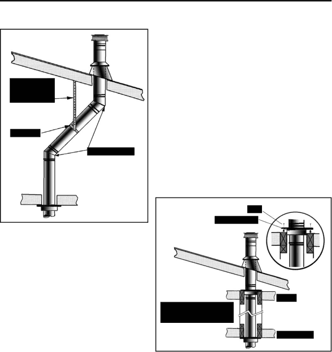
Enviro DV36 owner manual Use of Wall Straps

Page 26

Initial Installation

QUALIFIED INSTALLERS ONLY

NOTES:

(1)If an offset is necessary in the attic to avoid obstructions, it is important to support the vent pipe every 3 feet (914 mm), to avoid excessive stress on the elbows, and possible separation. Wall straps are available for this purpose (see Figure 36).

(2)When ever possible, use 45° degree elbows instead of 90° degree elbows. The 45° degree elbow offers less restriction to the flow of flue gases and intake air.

(3)For multi story installations; a ceiling firestop is required at the second floor, and any subsequent floors (see Figure 29). The opening should be framed to 10” (254 mm) x 10” (254 mm) inside dimensions, in the same manner as shown in Figure 29.

Figure 36: Use of Wall Straps.

(4)Any occupied areas above the first floor, including closets and storage spaces, which the vertical vent passes through, must be enclosed. The enclosure may be framed and sheet-rocked with standard building materials. However consult the appliance manufactures installation instructions for the minimum allowable clearance between the outside of the vent pipe, and the combustible surfaces of the enclosure. Do not fill any required air spaces with insulation.

Figure 37: Multi-Story Vent Pipe Installation.

26

Image 26
Contents For Your Safety R E C T V E N T F I R E P L a C ESafety Precautions GeneralTable of Contents This Enviro DV36 Fireplace Codes And ApprovalsVented GAS Fireplace Heater DV36 NG/LPG Specifications Installation OptionsFor Your Safety Read Before Operating InstructionsBlue, the fireplace is getting too much To Turn GAS Fireplace OFF Component Sound & ReasonMaintenance And Service Never Operate Fireplace with the glass Removed Bottom latches for glassKit Parts List Completely cooled downConversion Kit Installation Removing valve ScrewRing on valve screw Initial Installation Qualified Installers onlyDo not interfere with the structural integrity of the walls Mantel Clearances Vent Termination Restrictions Installation Instructions KIT ComponentsInstallation of Fireplace Horizontal Vent Kit Manufacturer Trade Name Nominal Sizes4DSC Two 2 piece wall Vent restrictor is located in the center Being Attached to Wood Assemble Vertical Vent TerminationRoof Pitch Minimum Height H Feet Meters Use of Wall Straps Installation of Electrical Wiring for the Optional FAN KIT GAS Line Connection To Test Valve PressuresSecondary Installation Empty firebox with grate and locator pinsThird Stage Log Set Installation Never operate the fireplace with the glass door removed Complete log set-up with embersTurn off the gas control knob and allow the unit to cool Back Panel In PlaceKit Contents Installation of Kit Hook Fan Tabs Over Grommets at Unit BackTrouble Shooting Problem Possible Cause SolutionParts List Reference Part Description Part NumberParts List Options Parts Diagram To the Distributor WarrantyTo the Dealer Installation Data Sheet