Exmark 4500-540 Rev. B manual Mobil HTS Grease Or Food-Grade Anti-seize, Deck Leveling

Page 33

Maintenance

which could cause binding of the OPC levers and erratic operation.

• Fuel tank studs, where studs are inserted into tank.

Mobil HTS Grease (Or Food-Grade Anti-seize)

Mobil HTS grease (or food-grade anti-seize) is used in the following locations:

Between the cutter housing spindle and bearings.

Between the cutter housing spindle and sheave.

Under top cutter housing bearing guard.

Adjustments

Note: Disengage PTO, shut off engine, wait for all moving parts to stop, engage parking brake, and remove key before servicing, cleaning, or making any adjustments to the unit.

Deck Leveling

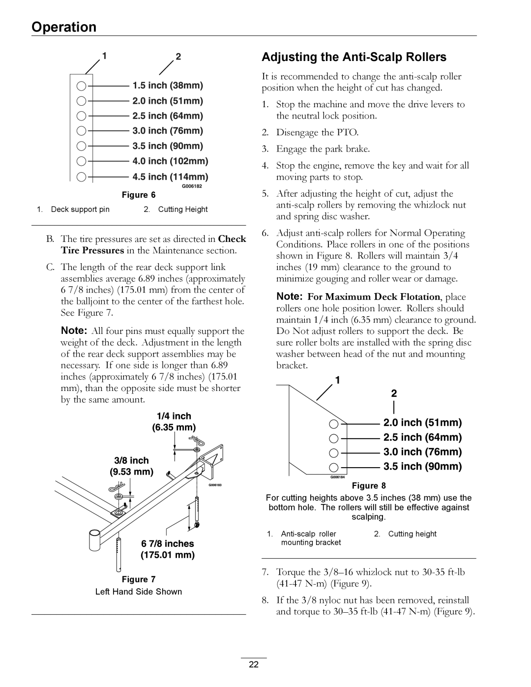
See Adjusting the Cutting Height section in Operation.

Pump Drive Belt Tension

Self-tensioning - No adjustment necessary.

Copper-Based Anti-seize

Copper-based anti-seize is used in the following locations:

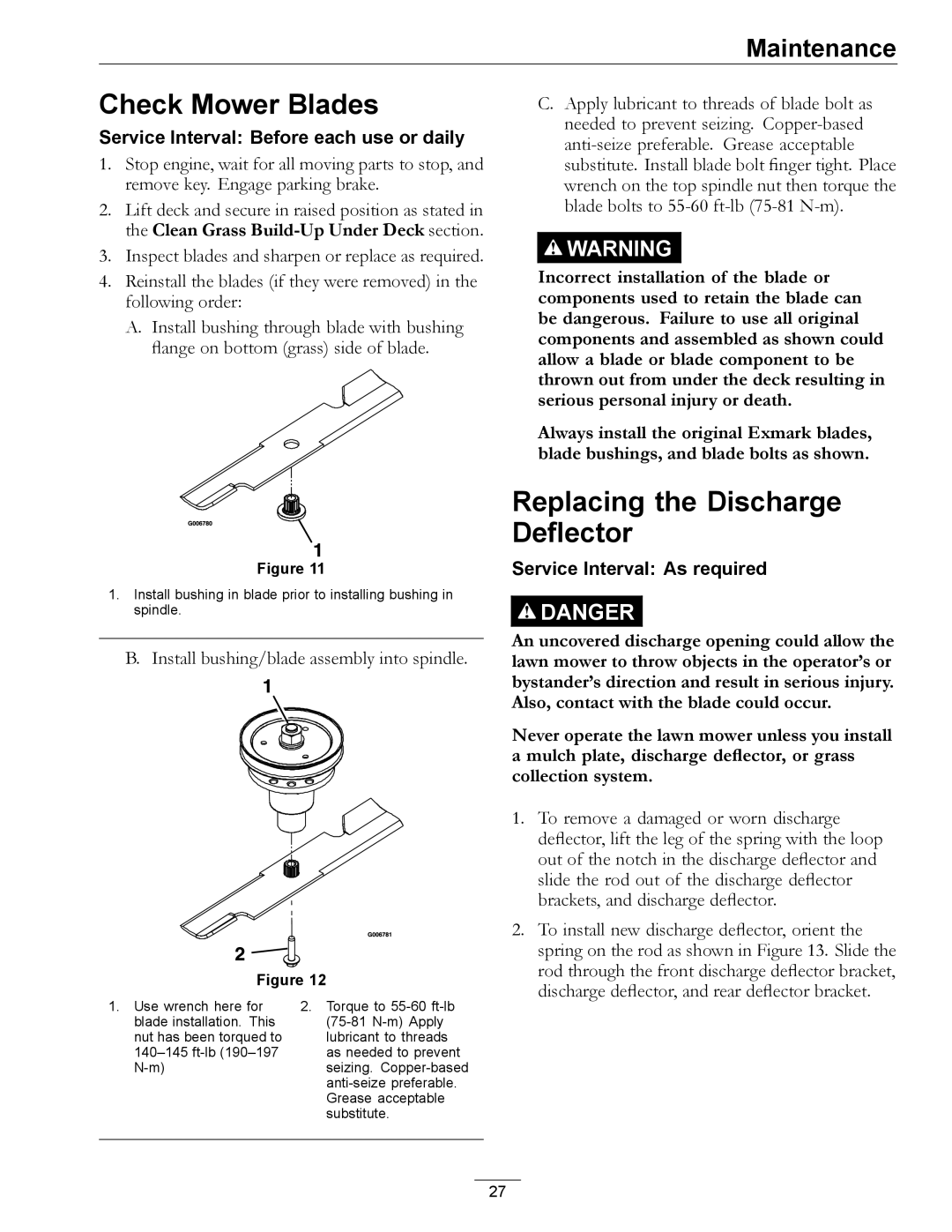
On threads of Blade Bolts. See Check Mower Blades section.

Between engine crankshaft and pump and blade drive sheaves.

On clutch arm assembly between bearings and shaft and between lower sheave and shaft.

Between pump shafts and sheaves.

Dielectric Grease

Dielectric grease is used on all blade type electrical connections to prevent corrosion and loss of contact.

PTO Clutching Belt Tension

See Inspect PTO Clutching Belt Tension section.

Deck Belt Tension

Self-tensioning - No adjustment necessary.

Park Brake Adjustment

1.Shut off engine and wait for all moving parts to stop.

2.Disengage the park brake.

3.Remove the hairpin in the park brake linkage. Turn the linkage in the yoke until there is 3/16 inch (4.8 mm) to 1/4 inch (6.4 mm) clearance between the park brake tire bars and the tires with the park brake disengaged. Re-install the hairpin.

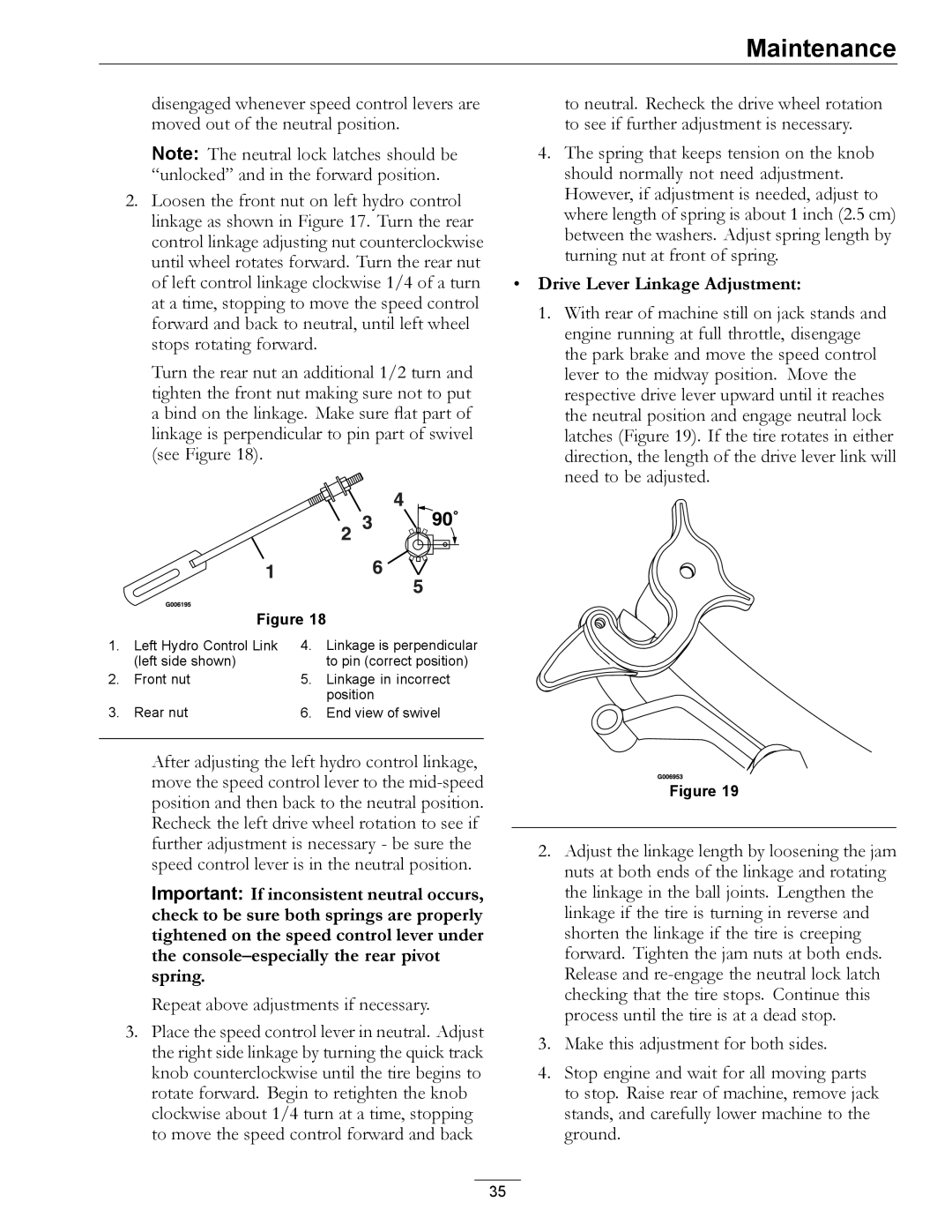
Hydro Drive Linkage

Adjustment

Adjust Speed Control Linkage and Neutral Safety Switch:

1.Stop engine and wait for all moving parts to stop. Engage parking brake. Remove key or spark plug wire(s).

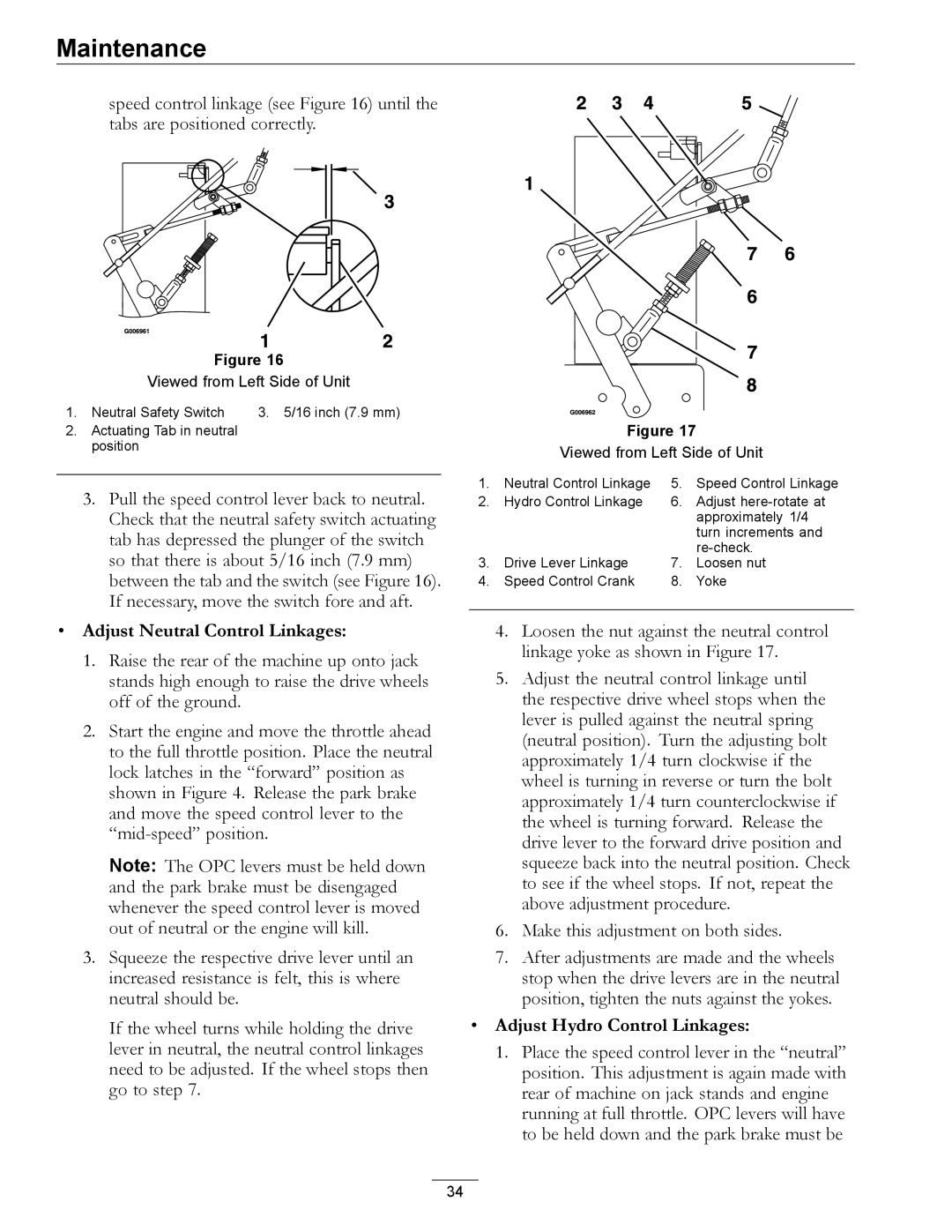
2.Move the speed control lever (located on the console) to the full forward position and check the orientation of the tabs on the ends of the speed control crank (see Figure 16). These tabs should be pointing straight down at the 6 o’clock position or slightly forward. Adjust the threaded yoke at the bottom of the

33
Image 33
Contents Turf Tracer HP California Introduction Contents Safety Alert Symbol SafetySafe Operating Practices TrainingSafety Slope Operation OperationMaintenance and Storage Safety Safety and Instructional Decals 413327 103-1977 109-3148 116-0404 117-2718 Specifications Model NumbersSystems Dimensions Torque Requirements Product OverviewControls OperationIgnition Switch Electric Start Only Off-Run Switch Manual Start OnlyTracking Adjustment Knob Park Brake LeverOperating Instructions Pre-StartOpen the Fuel Shut-Off Valve Starting the Engine Manual StartStopping the Engine Disengaging the PTODriving the Machine Drive Lever/Neutral Lock Latch OperationAdjusting the Cutting Height Driving ForwardDriving in Reverse Adjusting the Anti-Scalp Rollers Transporting a Unit TransportingRecommended Maintenance Schedules MaintenanceCheck Battery Charge Electric Start Units Only Check Engine Oil LevelProposition 65 Warning Do Not jump start a weak battery if these conditions exist Service Interval As requiredInstall bushing/blade assembly into spindle Check Mower BladesReplacing the Discharge Deflector Check Safety Interlock System Service Air CleanerCheck for Loose Hardware Check Hydraulic Oil Level Change Engine OilCheck Tire Pressures Check Condition Of Belts Change Fuel Filter Check Spark Plugs Change Hydraulic System Filter LevelHydraulic System Air Purge Wheel Hub-Slotted Nut Torque Specification Inspect PTO Clutching Belt TensionThread Locking Adhesives Hydro Drive Linkage Adjustment Park Brake AdjustmentMobil HTS Grease Or Food-Grade Anti-seize Deck LevelingAdjust Hydro Control Linkages Adjust Neutral Control LinkagesDrive Lever Linkage Adjustment Hydro Pump Spring Tension Setting Tracking AdjustmentPTO Safety Switch Retighten PTO switch mounting hardwareRemove Engine Shrouds and Clean Cooling Fins Clean Engine and Exhaust System AreaClean Debris From Machine Clean Grass Build-Up Under DeckMaintenance Problem Possible Cause Corrective Action TroubleshootingTroubleshooting Electrical Diagram SchematicsHydraulic Diagram Exmark Commercial Turf Equipment Page Date Description of Work Done Service Done By Service RecordPage This page may be copied for personal use See EXMARK’S Complete Line of Accessories and Options